How to Size a Plate Heat Exchanger: Key Steps and Considerations
Sizing a plate heat exchanger correctly is critical for achieving optimal thermal performance and avoiding costly oversizing or undersizing. This guide walks process engineers and purchasing managers through the essential steps—defining process parameters, calculating heat duty, selecting plate geometry, and verifying pressure drop. Whether you are working with gasketed, welded, or specialty designs, understanding these fundamentals ensures reliable operation across industries like chemical processing, HVAC, and food production.
Why Proper Sizing Matters for a Plate Heat Exchanger
A plate heat exchanger that is too small will fail to meet the required heat transfer rate, leading to process inefficiencies and potential equipment damage. On the other hand, an oversized unit adds unnecessary capital cost and may operate outside its design range, causing fouling or poor temperature control. Getting the sizing right from the start saves time, money, and maintenance headaches.
The sizing process revolves around a few core variables: flow rates, inlet and outlet temperatures, fluid properties, and allowable pressure drop. By systematically working through these, you can match the heat exchanger to your specific application—whether it is a simple liquid-to-liquid duty or a complex gas cooling scenario.
What Are the First Steps in Sizing a Plate Heat Exchanger?
Start by gathering the process data. You need the mass or volumetric flow rate for both the hot and cold streams, along with their specific heat capacities, densities, and viscosities at the average operating temperature. Then define the temperature program: the hot side inlet and outlet, and the cold side inlet and desired outlet.
With these numbers, calculate the heat duty (Q) using the formula Q = m × Cp × ΔT. This tells you how much thermal energy must be transferred per unit time. Once you have the duty, you can determine the required heat transfer area (A) from Q = U × A × LMTD, where U is the overall heat transfer coefficient and LMTD is the log mean temperature difference. The U value depends on plate material, corrugation pattern, and fluid properties—typical ranges for water-to-water duties are 3000–5000 W/m²K.
How Do Plate Geometry and Flow Configuration Affect Sizing?
Plate geometry is a key factor. Chevron angle, plate depth, and port size all influence the heat transfer coefficient and pressure drop. A high chevron angle (e.g., 60°) gives high turbulence and better heat transfer but also higher pressure drop. Low angles (e.g., 30°) are gentler on pressure but require more surface area.
Flow configuration also matters. Counter-current flow is standard for maximum thermal efficiency, but some applications use parallel or multi-pass arrangements. For viscous fluids or fluids with solids, consider a wide gap plate heat exchanger design to avoid clogging. SHPHE offers wide gap welded plate heat exchangers that handle fibrous or particulate-laden streams effectively.
Typical Parameter Ranges for Plate Heat Exchanger Sizing
The table below summarizes commonly accepted ranges for key sizing parameters. These are industry-generic values and should be verified with a manufacturer like SHPHE for your specific conditions.
| Parameter |
Typical Range |
| Heat transfer coefficient (U) – water/water |
3000–5000 W/m²K |
| Heat transfer coefficient (U) – steam/water |
1500–4000 W/m²K |
| Allowable pressure drop per stream |
20–100 kPa |
| Plate gap |
2–6 mm (standard), up to 15 mm (wide gap) |
| Maximum operating temperature (gasketed) |
180°C (with EPDM gaskets) |
| Maximum operating pressure (gasketed) |
25 bar |
Applications and Recommended Solutions for Different Duties
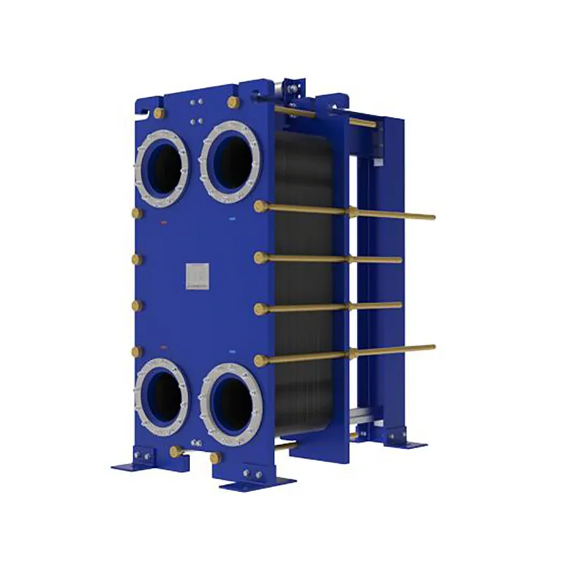
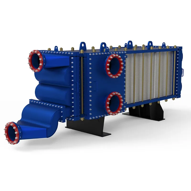
Different process conditions call for different plate heat exchanger types. For clean fluids with moderate temperatures and pressures, a gasketed plate heat exchanger is a cost-effective choice. SHPHE’s gasketed units are compatible with Alfa Laval and other major brands, making them a reliable alternative for retrofit or new installations.
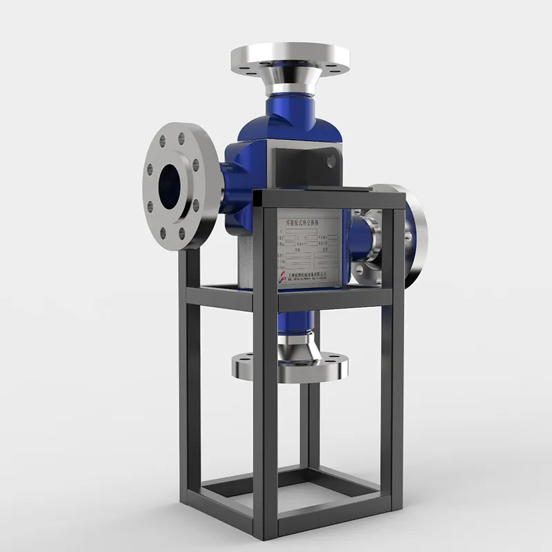
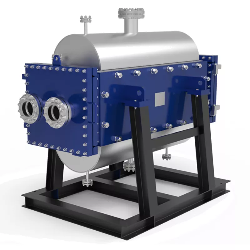
For high-temperature or high-pressure duties, consider a welded plate heat exchanger. SHPHE’s HT-Bloc and TP welded plate heat exchangers handle up to 400°C and 40 bar, ideal for chemical reactors or heat recovery from flue gases. If your fluid contains solids or fibers, the wide gap welded plate heat exchanger is the right fit, with plate gaps up to 15 mm to prevent fouling.
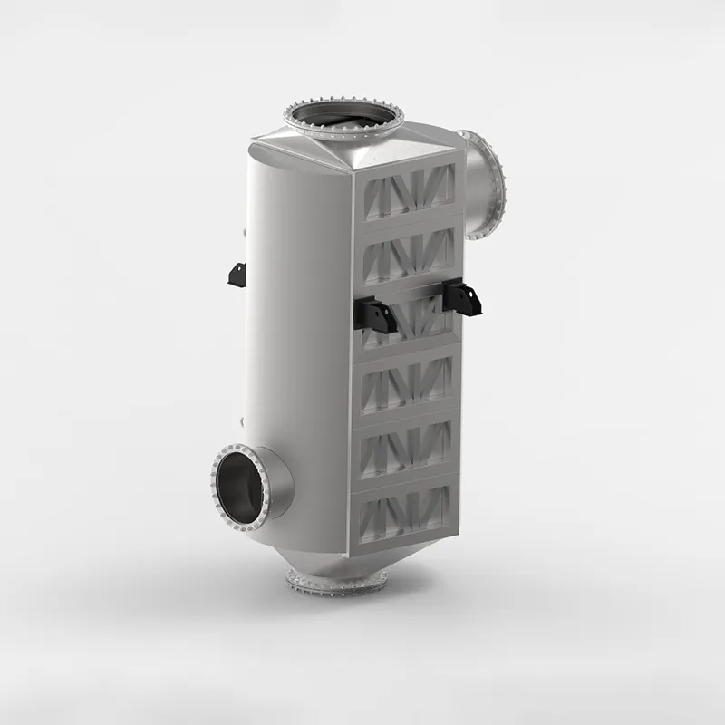
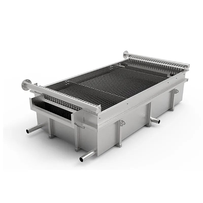
For compact, high-efficiency applications like LNG or high-pressure gas cooling, a printed circuit heat exchanger (PCHE) offers superior performance. SHPHE also provides custom-engineered plate air preheaters and pillow plates for specialized heat transfer needs in power generation and storage tank heating.
Why Choose SHPHE for Your Plate Heat Exchanger Needs?
SHPHE, founded in 2005 in Shanghai, is an ISO9001 and ASME U certified manufacturer exporting to over 20 countries. Our product range covers gasketed, welded, wide gap, PCHE, plate air preheaters, and pillow plates. We provide free thermal design and selection services, helping you size the right plate heat exchanger without guesswork.
Our engineering team uses advanced software to simulate your process conditions and recommend the optimal plate count, chevron pattern, and material combination. Whether you need a standard unit or a custom-engineered solution, we ensure the heat exchanger meets your performance targets within the allowed pressure drop.
Frequently Asked Questions About Plate Heat Exchanger Sizing
What is the most common mistake when sizing a plate heat exchanger?
The most common mistake is ignoring the effect of fluid viscosity on the heat transfer coefficient. Viscous fluids require lower flow velocities to avoid excessive pressure drop, which reduces turbulence and U value. Always use viscosity data at the average temperature, not just at inlet conditions.
Can I use the same sizing method for gasketed and welded plate heat exchangers?
Yes, the basic thermal sizing steps are the same. However, welded units often have different plate geometries and may handle higher pressures, so the allowable pressure drop and U value ranges differ. Consult the manufacturer’s data for accurate parameters.
How do I account for fouling in the sizing calculation?
Fouling is accounted for by adding a fouling resistance (Rf) to the overall heat transfer equation. Typical Rf values range from 0.0001 to 0.0005 m²K/W for clean fluids, and up to 0.001 for dirty streams. This increases the required surface area, so include it early in the design.
What is the role of the LMTD correction factor in sizing?
The LMTD correction factor (F) adjusts for deviations from pure counter-current flow. In multi-pass or cross-flow arrangements, F is less than 1, meaning you need more area. For single-pass counter-current, F is 1, which is why it is the preferred configuration.
Can SHPHE help with sizing if I only have partial data?
Absolutely. SHPHE’s free thermal design service can work with estimated values and refine the sizing as more data becomes available. We often help clients who have only flow rates and target temperatures, using industry-standard correlations to complete the design.
How does plate material selection affect sizing?
Plate material affects thermal conductivity and corrosion resistance. Stainless steel 316L is common, but titanium or Hastelloy may be needed for aggressive media. Lower conductivity materials require slightly more area, but the difference is usually small compared to the impact of fouling or flow conditions.
Request a Quote for Your Plate Heat Exchanger Sizing
To get an accurate sizing and quotation for your plate heat exchanger, please provide the following details: flow rate for each stream, inlet and outlet temperatures, operating pressure, and fluid type (including viscosity and specific heat if available). SHPHE’s team will use this data to recommend the optimal model and plate configuration.
Whether you need a gasketed plate heat exchanger for a clean water loop or a welded unit for aggressive chemicals, our free design service ensures you get the right size the first time. Contact us today with your process parameters, and we will deliver a tailored solution backed by 20 years of manufacturing expertise.

 English EN





User Comments
Service Experience Sharing from Real Customers
Marcus Chen
Lead Process EngineerWe were struggling with a 15°C approach temp on our old gasketed unit and this sizing guide literally walked me through the LMTD correction factor step-by-step. Used the example for a dairy pasteurizer and the actual performance matched the calculated duty within 3%. Finally a resource that doesn't assume you already know the fouling factor by heart.
Priya Kapoor
HVAC Design TechnicianNot gonna lie, I'm still a bit shaky on the pressure drop calculations for brazed plates, but the section on chevron angle selection for low-viscosity fluids saved my bacon on a chiller retrofit. Could use a few more real-world examples for ammonia systems, but for a free guide it's solid. Definitely bookmarking this.
Jack Morrison
Maintenance SupervisorI'm the guy who actually has to bolt these things back together on the floor, not the engineer who specs them. This guide helped me understand why the guys upstairs keep ordering plates with 60° herringbone patterns instead of the cheaper 30° ones. Less clogging on our cooling tower loop now. Simple language, no unnecessary math.
Elena Rossi
Graduate Process EngineerJust started in oil & gas and was totally lost on how to size a heat exchanger for a crude preheat train. The worked example with the TEMA-style nomenclature comparison (even though it's a plate unit) clicked for me. Only wish it had a quick-reference table for typical U-values for hydrocarbon services.