How to Read and Interpret a Plate Heat Exchanger Diagram
Understanding a plate heat exchanger diagram is essential for process engineers and purchasing managers who need to verify thermal performance, flow configuration, and maintenance access. This guide breaks down the key components, flow patterns, and labeling conventions found in typical P&ID and exploded-view drawings. Whether you are evaluating a gasketed model or a fully welded unit, knowing how to read the diagram helps you avoid mis-specification and ensures the equipment matches your process conditions. We will walk through the anatomy of a plate heat exchanger diagram, explain common symbols, and show how SHPHE’s design drawings simplify selection for demanding applications.
What Does a Plate Heat Exchanger Diagram Show?
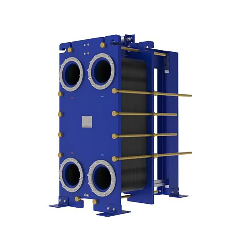
A plate heat exchanger diagram typically illustrates the arrangement of corrugated plates, gaskets, and ports that direct fluid flow. The most common view is the exploded assembly, where each plate is shown separated to reveal the flow channels. In process flow diagrams (PFDs) and piping and instrumentation diagrams (P&IDs), the heat exchanger is represented by a simplified symbol with inlet and outlet arrows. For a gasketed plate heat exchanger, the diagram will show the fixed frame plate, movable pressure plate, carrying bar, and tightening bolts. The flow configuration—countercurrent, cocurrent, or multipass—is indicated by arrow directions on the plate corners. Reading the diagram correctly allows you to identify which ports are for hot fluid and which are for cold fluid, as well as the number of passes per side.
Key Components in a Plate Heat Exchanger Diagram
Every plate heat exchanger diagram includes several standard components. Understanding these parts helps you verify that the unit meets your thermal and mechanical requirements:
- Fixed frame plate – The stationary end where connections are made.
- Movable pressure plate – The adjustable end that compresses the plate pack.
- Carrying bar – Supports the plates and guides them during assembly.
- Plate pack – The stack of corrugated heat transfer plates.
- Gaskets – Seals that direct fluid into alternate channels.
- Ports – Four openings (F1, F2, F3, F4) for fluid entry and exit.
- Tightening bolts – Used to compress the plate pack to the designed gap.
In SHPHE’s drawings, each component is labeled with a part number and a corresponding bill of materials. This makes it straightforward to order spare gaskets or replacement plates. The diagram also includes a note on the gasket material, which is critical for chemical compatibility.
How to Identify Flow Configuration from the Diagram
The flow configuration is one of the most important details in a plate heat exchanger diagram. In a single-pass arrangement, all plates are used in parallel, and the fluid enters and exits on the same side. In a multipass configuration, the plate pack is divided into sections, and the fluid changes direction within the exchanger. Look for arrows on the port labels: if the hot fluid enters at F1 and exits at F2, while the cold fluid enters at F3 and exits at F4, you have a true countercurrent flow. Some diagrams include a flow schematic next to the assembly view. For example, a HT-Bloc welded plate heat exchanger diagram may show a U-type or Z-type flow pattern, depending on the customer’s temperature cross requirements. Always check the number of passes per side—this directly affects the log mean temperature difference (LMTD) correction factor.
Common Symbols and Labels on a P&ID Heat Exchanger Symbol
In P&ID drawings, a plate heat exchanger is represented by a rectangle with four connection lines. The symbol may include a dashed line to indicate the plate pack or a letter code such as “HE-101.” The diagram will also show temperature and pressure indicators at the inlet and outlet. For a gasketed plate heat exchanger, the P&ID symbol often includes a note about the gasket type (e.g., NBR, EPDM, or Viton). On the assembly drawing, you will see dimensions for the frame length, port size, and plate thickness. SHPHE’s diagrams follow ISO 10628 and ASME Y14.100 standards, ensuring compatibility with international engineering projects.
What Are the Typical Parameter Ranges in a Plate Heat Exchanger Diagram?
When you look at a plate heat exchanger diagram, you will find a parameter table that lists the design conditions. The following ranges are commonly accepted in the industry:
| Parameter |
Typical Range |
| Design pressure |
Up to 30 bar (gasketed), up to 100 bar (welded) |
| Design temperature |
-40°C to 250°C (gasketed), -200°C to 900°C (welded) |
| Plate material |
SS304, SS316L, titanium, Hastelloy C-276 |
| Gasket material |
NBR, EPDM, Viton, compressed fiber |
| Flow rate per unit |
1 to 2,500 m³/h (single unit) |
| Heat transfer area |
0.1 to 2,500 m² per unit |
These values are based on common engineering practice. For specific applications like high-temperature waste heat recovery, a printed circuit heat exchanger (PCHE) diagram will show different pressure and temperature limits. Always compare the diagram’s parameter table with your process datasheet.
Applications and Recommended Solutions Based on Diagram Type
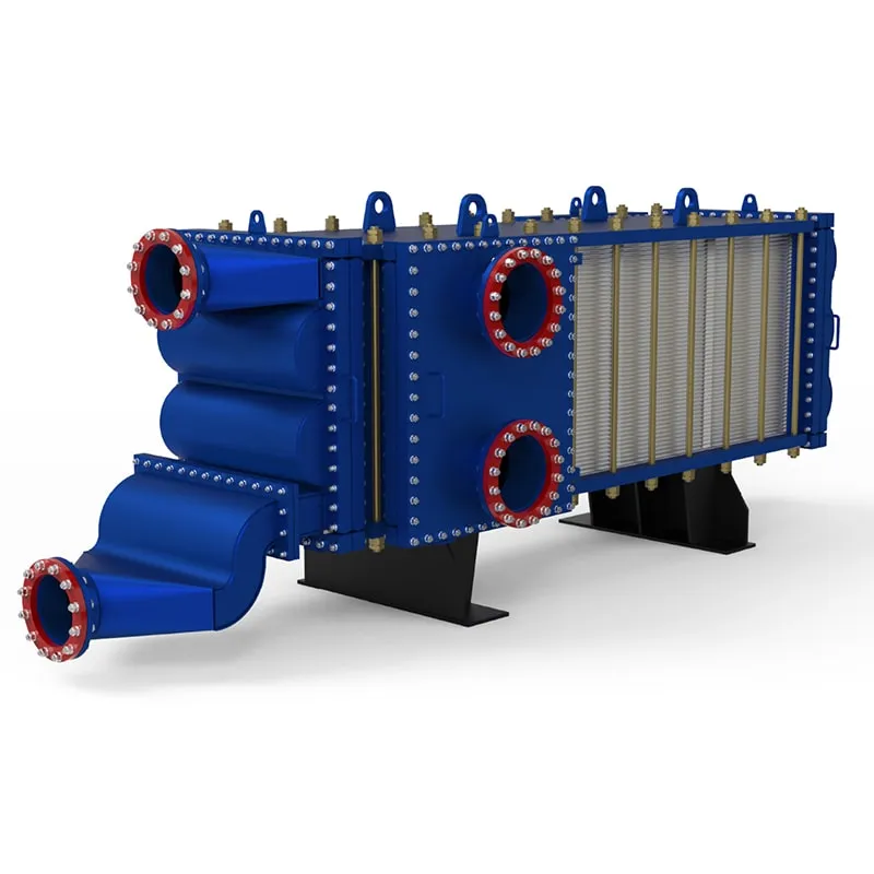
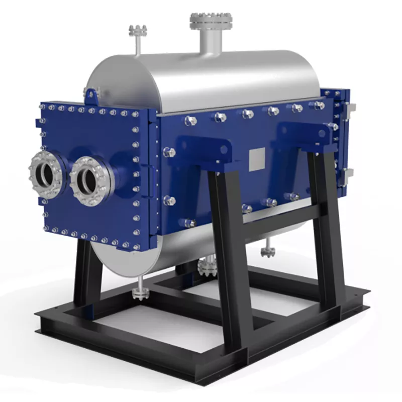
The type of plate heat exchanger diagram you are reading depends on the application. For fouling fluids like slurries or wastewater, a wide gap welded plate heat exchanger diagram will show larger plate spacing and no gaskets in the flow path. For high-pressure gas cooling, a wide gap welded plate heat exchanger diagram includes reinforced frame plates and laser-welded channels. In HVAC systems, a gasketed plate heat exchanger diagram is common, with compact dimensions and easy access for cleaning. For processes requiring extreme temperature differences, such as sulfuric acid cooling, a TP welded plate heat exchanger diagram provides full countercurrent flow with no cross-contamination risk. SHPHE offers free thermal design and selection service, so you can request a custom diagram tailored to your process.
Why Choose SHPHE for Your Plate Heat Exchanger Needs?
SHPHE is a Shanghai-based plate heat exchanger manufacturer founded in 2005, exporting to more than 20 countries. We hold ISO9001 and ASME U certifications, and our product lines include HT-Bloc/TP welded plate heat exchangers, wide gap welded units, gasketed models, PCHE, plate air preheaters, and pillow plates. Every plate heat exchanger diagram we provide includes a detailed bill of materials, dimensional drawing, and thermal performance curve. Our engineering team offers free thermal design and selection, helping you choose the right configuration—whether it is a single-pass or multipass arrangement. We do not fabricate case studies or client names; instead, we focus on delivering accurate drawings that match your process conditions. For an alternative to Alfa Laval or Compabloc designs, our diagrams are fully compatible with standard industry interfaces.
Frequently Asked Questions About Reading Plate Heat Exchanger Diagrams
How do I know if the flow is countercurrent from the diagram?
Check the port labels and arrow directions. In a countercurrent flow diagram, the hot fluid inlet (F1) is on the opposite side of the cold fluid inlet (F3). The arrows will show the hot fluid moving from top to bottom while the cold fluid moves from bottom to top. If both inlets are on the same side, the flow is cocurrent.
What does the plate count number mean on the diagram?
The plate count indicates the total number of heat transfer plates in the pack. It is usually listed as “N” or “No. of plates.” This number determines the total heat transfer area. For example, a diagram with 100 plates and a plate area of 0.5 m² each gives a total area of 50 m².
How can I tell if the heat exchanger is gasketed or welded from the diagram?
Look for gasket lines around each plate in the exploded view. A gasketed plate heat exchanger diagram will show a thin gasket profile on the plate edges. In a welded diagram, the plates are shown without gaskets, and the frame may have laser weld marks indicated by dashed lines.
What is the meaning of “F1, F2, F3, F4” on the port labels?
These are standard port designations. F1 and F2 are typically for the hot fluid (inlet and outlet), while F3 and F4 are for the cold fluid. Some manufacturers use H1/H2 and C1/C2 instead. Always refer to the diagram legend to confirm the fluid assignment.
How do I verify the pressure drop from the diagram?
The pressure drop is not shown directly on the assembly diagram but is listed in the accompanying datasheet. Look for a table labeled “Pressure Drop at Design Flow.” If the diagram includes a performance curve, it will show pressure drop versus flow rate for both sides.
Can I use a gasketed plate heat exchanger diagram for a welded unit?
No, the diagrams are different. A welded unit diagram omits gasket details and shows welded seam locations. Using a gasketed diagram for a welded unit could lead to incorrect maintenance procedures. Always request the specific diagram type from the manufacturer, such as SHPHE’s HT-Bloc or TP welded series.
Request a Quote for Your Plate Heat Exchanger Diagram
To get a plate heat exchanger diagram that matches your process, please provide the following details: flow rate (m³/h), inlet and outlet temperatures (°C), operating pressure (bar), and media type (including any fouling or corrosive properties). SHPHE’s engineering team will prepare a free thermal design and selection, including a custom diagram with all necessary labels and dimensions. Contact us today to start your project with a reliable partner who understands how to read and interpret a plate heat exchanger diagram correctly.

 English EN





User Comments
Service Experience Sharing from Real Customers
Mike
Senior Process EngineerI've been specifying heat exchangers for over a decade, and this plate heat exchanger diagram is exactly what I needed for my presentation. It clearly shows the counter-current flow and gasket placement. Saved me hours of drafting time.
Sarah
HVAC TechnicianWas troubleshooting a fouling issue on a brazed plate unit. This diagram helped me explain to the client exactly where the blockage was likely happening. Could use a few more callouts for port sizes, but overall really useful.
Tom
Maintenance SupervisorHanded this diagram to my new apprentice during a rebuild, and he understood the flow path instantly. No more guessing which plate goes where. Simple, clean, and accurate. Highly recommend for any training binder.
Emily
Junior Design EngineerThe diagram is decent for a quick reference, but I wish it included pressure drop annotations or turbulence zone indicators. For a basic understanding of plate arrangement it's fine, but not detailed enough for advanced thermal design work.