How Printed Circuit Heat Exchanger Solves High-Pressure Heat Transfer Challenges
Printed Circuit Heat Exchanger technology ensures safe, efficient, and reliable high-pressure heat transfer with compact design and superior mechanical integrity.
MoreJohn A. Smith, Thermal Engineering Group
Jun-09-2026
Accurate plate heat exchanger sizing begins with a precise definition of the thermal duty, which is the amount of heat that must be transferred between the hot and cold fluids per unit time. This is typically expressed in kilowatts (kW) or British thermal units per hour (BTU/h). The thermal duty is determined by the flow rates, specific heat capacities, and inlet/outlet temperatures of both fluid streams. Without a clear understanding of the required heat transfer rate, any subsequent sizing calculations will be unreliable, leading to either undersized or oversized equipment.
Equally critical are the physical and thermodynamic properties of the fluids involved. Key parameters include density, viscosity, specific heat capacity, thermal conductivity, and fouling tendency. These properties directly influence the heat transfer coefficient and pressure drop within the plate heat exchanger. For instance, fluids with high viscosity or a tendency to foul require special plate geometries or wider gap designs to maintain performance and cleanability. Accurate fluid data at both inlet and operating conditions are essential for reliable sizing.
The temperature program, including the approach temperature and temperature cross, must also be carefully defined. The approach temperature is the smallest temperature difference between the hot and cold fluids, while temperature cross occurs when the cold fluid outlet temperature exceeds the hot fluid outlet temperature. Plate heat exchangers are particularly well-suited for temperature cross applications due to their true countercurrent flow arrangement. However, this must be accounted for in the sizing algorithm to ensure the unit can achieve the required thermal performance.
Finally, the selection of appropriate safety margins and fouling factors is a necessary step in defining the thermal duty. Fouling factors account for the gradual accumulation of deposits on heat transfer surfaces over time, which reduces thermal efficiency. A balanced approach is required: excessive fouling allowances lead to oversized and costly heat exchangers, while insufficient allowances result in frequent cleaning cycles and operational downtime. Industry standards and historical operating data should guide the selection of these factors for each specific application.
The flow arrangement in a plate heat exchanger directly influences the temperature driving force available for heat transfer. Common configurations include counterflow, parallel flow, and crossflow, with counterflow providing the highest thermal efficiency due to a more uniform temperature difference along the plates.
The Log Mean Temperature Difference (LMTD) is the fundamental parameter used to quantify this effective driving force. It accounts for the changing temperature profiles of both fluids as they pass through the exchanger. The LMTD is calculated as:
LMTD = (ΔT1 - ΔT2) / ln(ΔT1 / ΔT2)
where ΔT1 and ΔT2 represent the temperature differences between the hot and cold fluids at each end of the heat exchanger. For plate heat exchangers, a correction factor (F) is often applied to the LMTD to account for deviations from pure counterflow or multipass configurations.
Accurate LMTD calculation is essential for proper sizing. Engineers must consider whether the flow is single-pass or multipass, as multipass arrangements reduce the effective temperature difference. Additionally, the selection of flow configuration affects pressure drop and thermal length, making it a critical decision in the design process. For more detailed guidance on flow configuration selection, refer to industry resources on plate heat exchanger design.
Pressure drop is a critical factor in plate heat exchanger design, directly influencing both pumping energy consumption and thermal performance. Higher pressure drop increases turbulence, enhancing heat transfer coefficients but also raising operational costs. Conversely, lower pressure drop reduces pumping expenses but may compromise heat transfer efficiency. The key is to find an optimal balance where the heat exchanger meets thermal duty without exceeding allowable pressure limits.
The following table illustrates typical pressure drop ranges and their impact on performance for common plate heat exchanger applications:
| Application | Allowable Pressure Drop (kPa) | Heat Transfer Coefficient (W/m²K) | Relative Pumping Cost |
|---|---|---|---|
| Water-Water (HVAC) | 30 - 70 | 3000 - 5000 | Low |
| Oil Cooling (Industrial) | 50 - 150 | 1500 - 3000 | Medium |
| Steam Heating (Process) | 20 - 80 | 4000 - 7000 | Low to Medium |
| High Viscosity Fluids | 100 - 250 | 500 - 1500 | High |
Designers must evaluate the trade-off between increased heat transfer and higher pumping costs. For low-viscosity fluids like water, a moderate pressure drop often yields optimal efficiency. For viscous fluids, wider plate gaps or specialized designs such as wide-gap welded plate heat exchangers may be necessary to avoid excessive pressure loss. Additionally, gasketed plate heat exchangers offer flexibility in adjusting plate count and configuration to fine-tune pressure drop.
Accurate sizing requires considering not only the initial pressure drop but also long-term operational costs. In systems where pumping energy is a major expense, selecting a heat exchanger with slightly lower pressure drop may result in significant savings over its lifecycle. For demanding applications, HT-Bloc welded plate heat exchangers provide robust performance under high pressure constraints.
Ultimately, the goal is to achieve the required thermal duty while keeping pressure drop within acceptable limits. This balance ensures reliable operation and cost-effectiveness, whether for standard HVAC systems or specialized industrial processes. Consulting with manufacturers like those offering custom-engineered pillow plates can help tailor solutions to specific pressure drop requirements.
The geometric configuration of plates directly governs thermal-hydraulic performance. Corrugation patterns (herringbone, chevron, or washboard) determine flow turbulence, heat transfer coefficients, and pressure drop. Chevron angles typically range from 30° to 65°, with higher angles increasing turbulence and thermal efficiency but also elevating pressure loss. Gap size between plates influences fluid velocity and residence time; narrower gaps enhance heat transfer but may restrict flow for viscous fluids or slurries. Material selection (stainless steel, titanium, Hastelloy, or nickel alloys) must consider corrosion resistance, temperature limits, and mechanical strength. Proper metallurgy ensures long-term reliability in aggressive chemical or high-temperature applications.
Plate thickness and surface finish also affect durability and fouling behavior. Thicker plates provide greater pressure capacity but reduce thermal conductivity slightly. Surface roughness or specialized coatings can mitigate scaling or improve cleanability. When sizing, engineers must balance corrugation geometry, gap dimensions, and material grade to achieve target heat duty while maintaining acceptable pressure drops and operational lifespan. For detailed product specifications, refer to engineering guidelines.
Fouling refers to the accumulation of unwanted deposits on heat transfer surfaces, which increases thermal resistance and reduces efficiency over time. Accurate sizing must incorporate fouling factors (typically expressed as m²·K/W) to ensure the heat exchanger maintains required performance after months or years of operation. Common fouling factors for plate heat exchangers range from 0.00005 to 0.0005 m²·K/W, depending on fluid type, temperature, and flow velocity.
A service margin (typically 10–25% additional surface area) is recommended to compensate for uncertainties in fouling rates, future process changes, or unexpected operating conditions. This margin prevents premature performance degradation and reduces maintenance frequency. For critical applications, consider using double-walled plates or enhanced surface geometries that mitigate fouling buildup. Designers should also account for cleaning intervals and accessibility when selecting plate spacing and gasket materials.
For detailed guidance on custom-engineered solutions that address fouling and long-term reliability, refer to gasketed plate heat exchangers or wide gap welded plate heat exchangers designed for viscous or fouling fluids. For extreme conditions, HT-Bloc welded plate heat exchangers offer robust construction with minimal fouling risk.
Accurate sizing begins with a precise definition of heat transfer requirements — including heat load, flow rates, inlet/outlet temperatures, and fluid characteristics such as specific heat, viscosity, density, and thermal conductivity. These parameters directly influence the required surface area and the selection of plate geometry.
The log mean temperature difference (LMTD) provides the effective thermal driving force, which must be corrected for flow arrangement (counterflow, parallel flow, or multipass). A correct LMTD ensures that the exchanger is neither undersized (risk of duty shortfall) nor oversized (excess capital cost).
Pressure drop limits govern pumping energy and operating cost. A balanced design optimizes the trade‑off between high heat transfer coefficients (enhanced by turbulence) and acceptable pressure loss. Both allowable side drops (hot and cold) must be respected to avoid excessive pump power or flow maldistribution.
Corrugation pattern (chevron angle, depth), gap size, and plate thickness directly affect heat transfer, pressure drop, and mechanical strength. Material metallurgy must resist corrosion, erosion, and temperature extremes while ensuring compatibility with both fluids. Gasket materials also set temperature and pressure limits.
Fouling resistance (fouling factor) accounts for gradual deposit buildup on heat transfer surfaces. A realistic service margin — typically 10‑25% extra surface area — ensures the exchanger can maintain duty over extended operation without excessive cleaning or performance drop. This margin also covers uncertainties in fluid properties and operating conditions.
A reliable plate heat exchanger sizing integrates all five aspects: thermal duty, LMTD, pressure drop, plate geometry, and fouling allowance. Ignoring any parameter can lead to off‑design performance, higher lifecycle costs, or premature failure. Systematic evaluation of these interdependent factors enables a robust, cost‑effective heat exchanger specification.
We provide you with comprehensive foreign trade solutions to help enterprises achieve global development
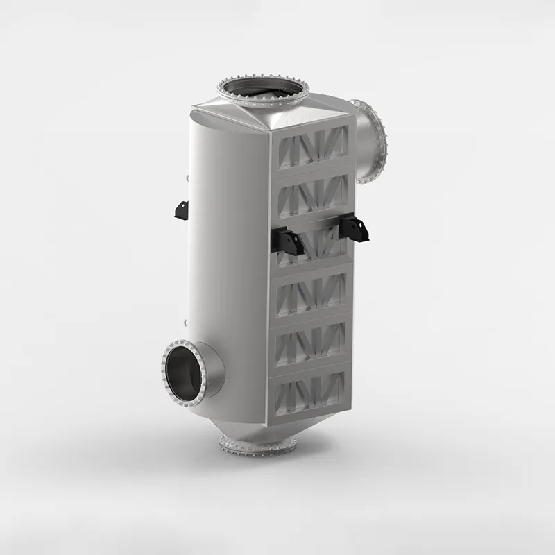
Industrial furnace and boiler exhaust gases carry vast amounts of unutilized thermal energy. The SHPHE custom Plate Air Preheater (PAPH) is target-engineered to intercept this high-temperature flue gas, recovering valuable waste heat and transferring it directly back to incoming combustion air or process gas streams. By substantially elevating the temperature of your flame feed, our custom systems optimize combustion thermodynamics, deliver massive fuel savings, and significantly reduce industrial carbon and emissions footprints. Built to withstand severe flue-gas environments, SHPHE PAPH systems serve as the premier choice for modern, energy-intensive plants prioritizing decarb compliance and maximum thermal efficiency.
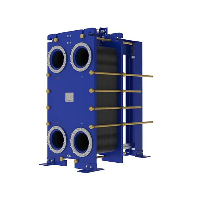
Since the invention of the plate heat exchanger (PHE) in 1923, thermal technology has evolved from standard food-grade processing to highly complex industrial operations. At SHPHE, we take this classic, versatile design and transform it into highly bespoke heat transfer solutions tailored to your unique process fluids and thermal loads. While traditional gasketed PHEs offer high efficiency and compact footprints, SHPHE optimizes plate corrugations, metallurgy, and sealing systems to handle your specific chemical, HVAC, or energy recovery parameters. Our custom-engineered gasketed plate heat exchangers provide outstanding scalability and ease of maintenance, serving as an indispensable asset for heavy industries—including oil and gas, metallurgy, and food processing—where uptime, energy recovery, and long-term sustainability are top priorities.
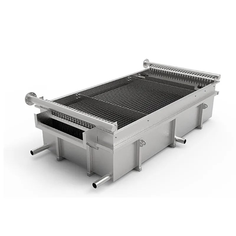
Originated in the mid-20th century to bypass the manufacturing bottlenecks and weight limitations of standard jacketed thermal components, the Pillow Plate (also known as a dimple plate or embossed plate) has revolutionized precision fluid-wall engineering. At SHPHE, we take this highly flexible technology and elevate it into a core foundation for bespoke industrial heat transfer integration. By utilizing state-of-the-art automated CNC fiber laser welding, our engineers customize the mechanical inflation profiles and spot pitch grids to directly match your specific fluid dynamics, pressure limits, and vessel configurations. Today, SHPHE's custom pillow plates are indispensable assets for worldwide processing plants prioritizing advanced thermal performance, zero-leak safety, and hygienic processing—serving as the definitive solution across food, pharmaceutical, chemical, and bulk solids cooling sectors.
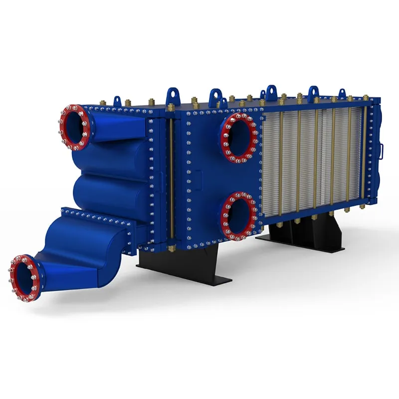
Custom-Engineered Anti-Clogging Solutions for High-Viscosity Slurries: Deployed specifically to conquer severe industrial fouling, SHPHE wide gap welded plate heat exchangers are tailor-built to handle complex media containing dense fibers, coarse crystals, or solid suspensions without clogging. Each non-obstructed channel is calculated and formed by laser-welded plate packs matching your fluid’s exact rheology and grain size, completely eliminating structural "dead zones" and media stagnation. Available in highly compact vertical and versatile horizontal configurations, our vertical engineering drastically reduces plant footprints while maintaining unhindered product throughput, minimal pressure drops, and flawless continuous operations across harsh process loops.
Select the most popular foreign trade service products to meet your diverse needs
Industrial furnace and boiler exhaust gases carry vast amounts of unutilized thermal energy. The SHPHE custom Plate Air Preheater (PAPH) is target-engineered to intercept this high-temperature flue gas, recovering valuable waste heat and transferring it directly back to incoming combustion air or process gas streams. By substantially elevating the temperature of your flame feed, our custom systems optimize combustion thermodynamics, deliver massive fuel savings, and significantly reduce industrial carbon and emissions footprints. Built to withstand severe flue-gas environments, SHPHE PAPH systems serve as the premier choice for modern, energy-intensive plants prioritizing decarb compliance and maximum thermal efficiency.
Originated in the mid-20th century to bypass the manufacturing bottlenecks and weight limitations of standard jacketed thermal components, the Pillow Plate (also known as a dimple plate or embossed plate) has revolutionized precision fluid-wall engineering. At SHPHE, we take this highly flexible technology and elevate it into a core foundation for bespoke industrial heat transfer integration. By utilizing state-of-the-art automated CNC fiber laser welding, our engineers customize the mechanical inflation profiles and spot pitch grids to directly match your specific fluid dynamics, pressure limits, and vessel configurations. Today, SHPHE's custom pillow plates are indispensable assets for worldwide processing plants prioritizing advanced thermal performance, zero-leak safety, and hygienic processing—serving as the definitive solution across food, pharmaceutical, chemical, and bulk solids cooling sectors.
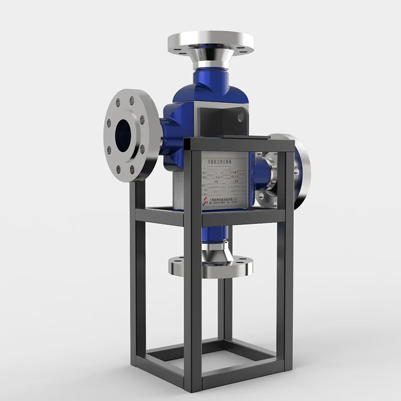
The SHPHE Printed Circuit Heat Exchanger (PCHE) represents a paradigm shift in microchannel thermal management, meticulously engineered for the world's most critical and demanding industrial boundaries. Developed to surpass the physical limitations of conventional shell-and-tube designs in ultra-high-pressure environments, our custom PCHEs integrate advanced photochemical etching and solid-state diffusion bonding to provide unmatched safety, thermal efficiency, and integrity under extreme stress. Initially deployed within high-consequence sectors such as aerospace and nuclear power generation, PCHE technology has completely revolutionized high-density thermal processing. Today, SHPHE brings this breakthrough engineering to mainstream energy transitions—including LNG liquefaction, supercritical CO² power cycles, hydrocarbon processing, and high-pressure hydrogen systems—enabling plants to maximize energy recovery, ensure zero-leakage security, and significantly shrink environmental footprints.


User Comments
Service Experience Sharing from Real Customers
Maggie
Senior Process EngineerWe were struggling with a tight retrofit project where floor space was zero. Ran the sizing numbers through this tool and it nailed the plate count and pressure drop within 3% of our field test. Saved us from overbuying a frame we didn't need. Highly recommend for anyone doing MEP upgrades.
Tommy
HVAC TechnicianNot gonna lie, I usually just swap like-for-like when a chiller plate goes bad. But I had to size a new one for a weird old brewery system and this guide made it simple. Plugged in the flow and temps, got a model number that fit perfectly. No leaks, no drama. Exactly what I needed.
Lena
Mechanical Design EngineerI'm a junior engineer and have been dreading heat exchanger calculations since college. This sizing approach broke down the NTU and LMTD steps in a way that actually clicked for me. My senior checked my work and didn't change a thing. First time I've felt confident specifying a plate heat exchanger on my own.
Dexter
Plant Maintenance ManagerHad a sudden failure on a milk pasteurizer line on a Friday afternoon. Used this sizing method to emergency-order a replacement plate pack over the weekend. Monday morning it bolted right into the existing frame and we were back online by lunch. The thermal performance is spot on. Saved my weekend and my production quota.