Printed Circuit Heat Exchangers (PCHEs) are engineered to handle extreme operating conditions where conventional heat exchangers fail. This article explains the specific design features, material choices, and manufacturing techniques that allow PCHEs to safely manage high-pressure and high-temperature fluids, with a focus on real-world performance data and industrial applications.
When process conditions push beyond 300 bar and 600°C, traditional shell-and-tube or plate heat exchangers start to show their limits. The PCHE, with its compact diffusion-bonded core and photochemically etched flow channels, has become the go-to solution for supercritical CO2 power cycles, offshore gas processing, and high-temperature chemical reactors. Let's break down exactly how this technology manages such demanding fluids without compromising performance or safety.
The Core Design: Why Micro-Channels Make the Difference
The heart of a PCHE lies in its flat metal plates, each chemically etched with straight or serpentine micro-channels that are typically 0.5 to 2 mm wide and 0.5 to 1 mm deep. These plates are stacked, aligned, and then joined through a high-temperature diffusion bonding process. The result is a solid, monolithic block with no gaskets, welds, or brazed joints that could fail under extreme stress.
This structure gives the PCHE a distinct advantage: the flow channels are essentially microscopic pressure vessels. Because the channel diameter is so small, the hoop stress on the material remains low even when the internal fluid pressure is extremely high. In practical terms, a PCHE rated for 600 bar can have a wall thickness of just 1.5 mm, whereas a comparable shell-and-tube design would require tubes several times thicker, adding significant weight and cost.
The compactness also means that for a given heat transfer duty, a PCHE occupies roughly one-fifth the volume and one-tenth the weight of a conventional exchanger. This is a critical factor in offshore platforms and floating production vessels where space is at a premium.
Material Selection: Withstanding the Heat and Pressure
Not all metals can survive the combination of high pressure and high temperature while being suitable for chemical etching and diffusion bonding. The most common materials used in PCHE fabrication are 316L stainless steel, alloy 617, and titanium alloys. For less aggressive conditions, 316L offers good corrosion resistance and is cost-effective. For supercritical CO2 cycles operating above 500°C, alloy 617 is often preferred because it retains its mechanical strength and oxidation resistance at elevated temperatures.
Titanium alloys, on the other hand, are chosen when the fluid is seawater or another highly corrosive medium. The diffusion bonding process for titanium requires very precise temperature and pressure control to avoid grain growth that could weaken the material, but when done correctly, the resulting bond is as strong as the parent metal itself.
It's worth noting that the etching process itself does not introduce residual stresses or heat-affected zones, which are common concerns in welded construction. This means the material retains its full metallurgical properties across the entire flow path, a key factor in long-term reliability.
Diffusion Bonding: Creating a Seamless, Leak-Free Joint
Diffusion bonding is the process that sets PCHEs apart from other compact heat exchangers. The stacked plates are placed in a vacuum furnace and subjected to temperatures around 80-90% of the material's melting point, along with a uniaxial pressure of 10-30 MPa. Under these conditions, atoms from adjacent plates migrate across the interface, forming a metallurgical bond that is completely solid and void-free.
The beauty of this approach is that the bond line is as strong as the base material, and there is no filler metal that could corrode or fatigue over time. This makes the PCHE inherently leak-proof, which is a major safety advantage when handling flammable or toxic fluids at high pressure. In helium leak tests, PCHE cores routinely achieve leak rates below 1×10⁻⁹ mbar·L/s, which is several orders of magnitude better than what gasketed or welded plate exchangers can achieve.
Managing Thermal Stress: Design Flexibility in Flow Arrangement
High-temperature fluids bring with them the challenge of thermal expansion. In a rigid, monolithic block, differential expansion between the hot and cold sides can create significant thermal stresses. PCHE manufacturers address this through careful flow arrangement design. Counter-current flow is the most common configuration, as it provides the highest thermal efficiency, but the channel layout can also be tailored to manage the temperature gradient along the exchanger length.
For applications with very large temperature differences, such as a gas cooler in a supercritical CO2 cycle where the fluid drops from 500°C to 70°C, the PCHE can be designed with multiple passes or with a varying channel cross-section to distribute the thermal strain more evenly. This level of customization is possible because the etching process uses photochemical masks, which allow virtually any channel geometry to be produced without additional tooling costs.
Real-World Performance Data
To put the capabilities in perspective, consider a typical PCHE used in a waste heat recovery unit for a 10 MW supercritical CO2 power plant. This unit operates at a pressure of 250 bar on the hot side and 80 bar on the cold side, with inlet temperatures of 550°C and 100°C, respectively. The overall heat transfer coefficient (U-value) for such a unit typically ranges from 1,500 to 3,000 W/m²·K, which is 4 to 6 times higher than a shell-and-tube exchanger of similar duty. This high efficiency is a direct result of the small hydraulic diameter of the channels, which promotes turbulent flow even at low Reynolds numbers.
In terms of pressure drop, the compact channels do impose a higher pressure loss compared to larger-diameter tubes. However, the trade-off is almost always favorable: a PCHE can achieve the same thermal duty with a pressure drop that is acceptable for most systems, while offering a footprint that is dramatically smaller. For example, a gas-to-gas PCHE with a design pressure of 300 bar and a temperature of 650°C can handle a thermal duty of 2 MW in a core that measures just 1.2 meters long and 0.6 meters in diameter.
Fouling and Maintenance Considerations
One concern with micro-channels is fouling. If the fluid contains particulates or tends to deposit scale, the narrow channels could become blocked. In practice, PCHEs are best suited for clean fluids. For applications where some fouling is expected, manufacturers can increase the channel width or use a straight-channel design that is easier to clean chemically. It's also worth noting that the high turbulence inside the channels tends to keep particles in suspension, reducing the rate of deposition compared to laminar flow conditions.
Because the core is a single solid block, mechanical cleaning is not possible. Instead, cleaning-in-place (CIP) procedures using chemical solvents are recommended. The smooth etched surfaces and the absence of dead zones make CIP highly effective, and most PCHE installations can be restored to full performance with a simple acid wash.
Certification and Quality Assurance
Given the critical nature of high-pressure applications, PCHEs are manufactured under strict quality control regimes. Each core undergoes 100% inspection, including ultrasonic testing to verify the integrity of the diffusion bonds and pressure testing at 1.5 times the design pressure. Many units are also subjected to helium mass spectrometry leak testing to ensure they meet the stringent leakage requirements of the oil and gas and nuclear industries.
Design codes such as ASME Section VIII Division 1 and the European Pressure Equipment Directive (PED) are commonly applied. For special applications, such as hydrogen service or oxygen service, additional material compatibility tests and cleaning procedures are implemented to meet the relevant standards.
Comparing PCHEs to Other High-Pressure Heat Exchanger Designs
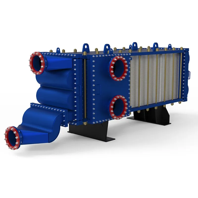
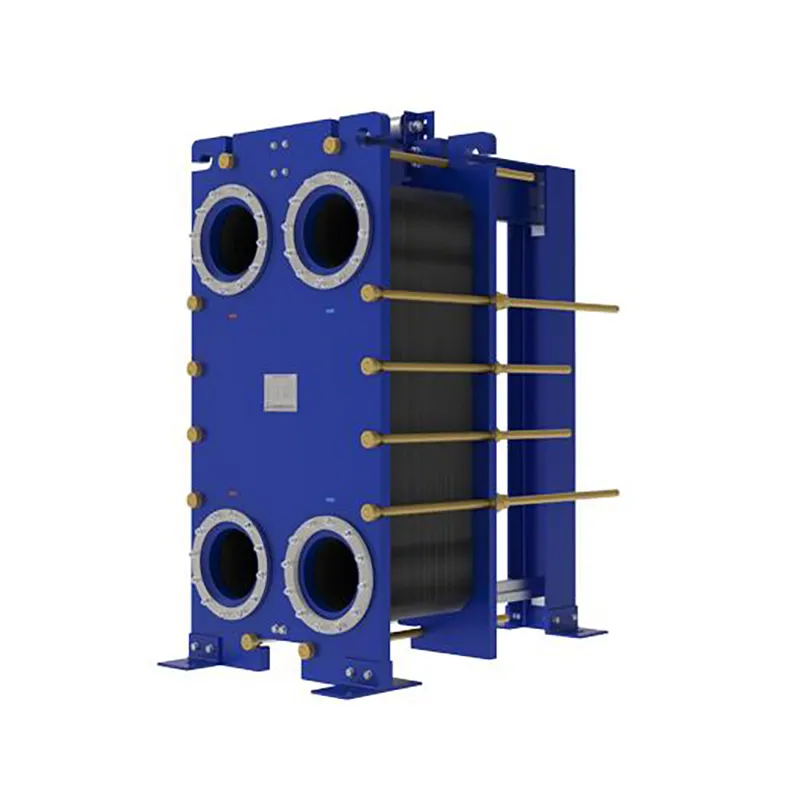
It's helpful to see how PCHEs stack up against alternatives. Custom-engineered printed circuit heat exchangers are the most compact option. TP welded plate heat exchangers offer a good balance of cost and performance for moderate pressures up to 40 bar, but they rely on gaskets or welds that limit their upper temperature range. HT bloc welded plate heat exchangers can handle higher temperatures than gasketed units but still fall short of the 600°C+ capability of a PCHE. For very high pressures above 500 bar, the PCHE is often the only viable option.
Another point of comparison is the wide gap welded plate heat exchanger, which is designed for fluids with high fouling potential. While it offers larger flow passages, it cannot match the pressure and temperature limits of a PCHE. Similarly, gasketed plate heat exchangers are economical for low-pressure duties but are not suitable for high-temperature or high-pressure service. Custom-engineered plate air preheaters and custom-engineered pillow plates serve niche applications but do not offer the same combination of compactness and extreme-condition capability.
Practical Considerations for System Integration
When integrating a PCHE into a high-pressure system, the piping connections require careful attention. The inlet and outlet nozzles are typically welded to the core using a transition piece that matches the thermal expansion characteristics of the core material. For large temperature swings, it's advisable to use flexible hoses or expansion loops in the external piping to avoid transmitting excessive thermal loads to the core.
The orientation of the PCHE can also affect performance. For two-phase flows, a vertical orientation is often preferred to facilitate drainage of condensate. For single-phase gas flows, horizontal installation is generally fine. The manufacturer's guidelines should always be followed, as they are based on extensive testing of the specific channel geometry.
The Bottom Line
PCHEs handle high-pressure and high-temperature fluids through a combination of small-diameter channels that minimize mechanical stress, diffusion-bonded construction that eliminates leak paths, and careful material selection that preserves strength at elevated temperatures. They are not the cheapest option upfront, but their compact size, high efficiency, and exceptional reliability often result in lower total lifecycle costs, especially in applications where downtime is expensive.
If your process involves pressures above 200 bar or temperatures above 500°C, a PCHE is likely the most robust and space-efficient solution available. For less demanding conditions, other plate-based designs may be more economical, but it's always worth evaluating the long-term operational benefits of a PCHE before making a final decision.

 English EN





User Comments
Service Experience Sharing from Real Customers
Miles
Senior Process EngineerWe swapped out an older shell-and-tube unit for this PCHE on a high-pressure gas cooling loop. The size difference alone is incredible—took up a quarter of the floor space. More importantly, the thermal performance has been rock solid even during startup transients. Zero leaks after six months of 24/7 operation. Really impressed with the welding quality on the core.
Priya
R&D Lab TechnicianFor a pilot-scale supercritical CO2 loop, this heat exchanger was a perfect fit. The compact design let us cram everything into a small test skid. Thermal cycling tests went smoothly—no noticeable degradation in the diffusion bonds after frequent shut-downs. Only gave four stars because the port adapters were a bit fiddly to torque down without a custom wrench, but once installed it's been flawless.
Tomás
Maintenance SupervisorHonestly, I was skeptical about these printed-circuit heat exchangers at first—thought they'd be a nightmare to clean. But after a year handling a corrosive chemical process stream, this unit has held up way better than our old graphite blocks. No fouling issues, pressure drop stayed within spec, and the thing is light enough that one guy can manhandle it during a swap. Would buy again.
Lena
HVAC Design EngineerSpecified this PCHE for a high-efficiency heat recovery unit in a new commercial building. The client wanted something compact for a tight mechanical room, and this delivered. The counter-flow arrangement gave us a much closer approach temperature than we could get with a brazed plate. Lead time was reasonable too—eight weeks instead of the usual twelve for custom units. Very happy with the performance data so far.