How Printed Circuit Heat Exchanger Solves High-Pressure Heat Transfer Challenges
Printed Circuit Heat Exchanger technology ensures safe, efficient, and reliable high-pressure heat transfer with compact design and superior mechanical integrity.
MoreAuthor: Heat Transfer Analysis Team
Date: June 9, 2026
Multipass heat exchangers achieve significantly higher heat transfer rates than single-pass designs primarily through four interconnected mechanisms that enhance the thermal driving force and surface utilization. First, by redirecting the tube-side fluid through multiple passes, the flow arrangement approximates true countercurrent flow, which maximizes the logarithmic mean temperature difference (LMTD) compared to the less efficient parallel or cross-flow configurations typical of single-pass units. Second, the increased fluid velocity resulting from dividing the total flow area into multiple passes raises the Reynolds number, promoting turbulent flow that substantially improves convective heat transfer coefficients on the tube side. Third, the extended heat transfer surface area per unit volume, achieved by routing the fluid through multiple tube bundles within the same shell, provides more area for thermal exchange without proportionally increasing the equipment footprint. Additionally, the repeated flow direction changes and tube bundle configurations introduce secondary flow effects and mixing that further disrupt thermal boundary layers. However, these thermal performance gains come with trade-offs, including higher pressure drops across the heat exchanger, which increase pumping power requirements and operational costs, as well as potential issues with fouling and maintenance complexity. Despite these drawbacks, the thermal advantages of multipass configurations make them widely preferred in applications where compactness and high heat flux are critical, such as in power generation, chemical processing, and HVAC systems.
In multipass heat exchangers, the fluid is redirected through multiple passes, which significantly increases the flow velocity compared to single-pass designs. Higher velocity directly enhances the convective heat transfer coefficient, as described by the Dittus-Boelter correlation: Nu = 0.023 Re^0.8 Pr^n. A higher Reynolds number (Re), driven by increased velocity, leads to a thicker turbulent boundary layer and thinner laminar sublayer, reducing thermal resistance.
Turbulence plays a critical role by promoting fluid mixing and disrupting the thermal boundary layer. Multipass configurations create flow disturbances at each turn and baffle, generating eddies that transport heat more effectively from the wall to the bulk fluid. This turbulent mixing increases the Nusselt number (Nu) and, consequently, the overall heat transfer coefficient (U).
The combined effect of higher velocity and enhanced turbulence in multipass designs yields heat transfer rates 20-50% greater than equivalent single-pass units, making them ideal for applications requiring compact size and high thermal efficiency, such as in chemical processing and HVAC systems.
In a multipass heat exchanger, the tube bundle is divided into several passes, allowing the fluid to flow back and forth across the shell side multiple times. This design inherently increases the effective heat transfer surface area per unit volume compared to a single pass configuration, where the fluid travels in one straight path. By forcing the tube-side fluid to traverse the shell multiple times, the velocity and turbulence are enhanced, leading to a higher overall heat transfer coefficient.
The extended surface area utilization is achieved without physically adding more tubes; instead, the same tubes are used more effectively by redirecting the flow. This results in a compact design with improved thermal performance, particularly in applications where space is constrained and high efficiency is required.
| Parameter | Single Pass Design | Multipass Design (4 Pass) |
|---|---|---|
| Effective Tube Length (m) | 6.0 | 6.0 |
| Number of Tube Passes | 1 | 4 |
| Total Flow Path Length (m) | 6.0 | 24.0 |
| Heat Transfer Area (m²) | 18.8 | 18.8 |
| Effective Surface Utilization Factor | 1.0 | 1.7 |
The table above illustrates that while the nominal heat transfer area remains identical, the multipass design significantly increases the effective surface utilization factor due to repeated exposure of the tube surface to the shell-side fluid. This leads to a higher temperature gradient and improved thermal efficiency without increasing the physical footprint of the exchanger.
For further technical details on custom engineered plate heat exchangers, please refer to the product documentation available at: Plate Air Preheaters, Pillow Plates, and Printed Circuit Heat Exchangers.
In multipass heat exchangers, the flow arrangement closely approximates pure countercurrent flow even when the physical configuration involves multiple tube or channel passes. This approximation is achieved by directing the two fluid streams in opposite directions over the effective heat transfer length, which maximizes the temperature gradient between the fluids along the entire surface.
The logarithmic mean temperature difference (LMTD) for countercurrent flow is inherently larger than that for parallel or crossflow arrangements under the same inlet and outlet temperature conditions. By approximating countercurrent behavior, multipass designs achieve a higher effective LMTD, which directly increases the heat transfer rate according to the equation Q = U × A × LMTD, where U is the overall heat transfer coefficient and A is the surface area.
Additionally, the countercurrent approximation reduces the temperature cross and allows for closer approach temperatures between the hot and cold streams. This thermodynamic advantage enables multipass exchangers to recover more heat energy from the same inlet conditions compared to single-pass designs, making them more efficient for applications requiring high temperature effectiveness.
The impact on LMTD is quantifiable through correction factors applied to the pure countercurrent LMTD. In multipass configurations, these correction factors remain close to unity over a wide range of operating conditions, whereas single-pass crossflow or parallel flow arrangements often require significant derating. This mathematical advantage translates directly into reduced surface area requirements or increased thermal duty for a given exchanger size.
While multipass heat exchangers significantly enhance heat transfer rates through increased flow velocity and extended residence time, these thermal benefits come at the cost of higher pressure drop across the unit. The additional passes force the fluid to travel a longer path and undergo directional changes, resulting in greater frictional losses. Consequently, the pumping power required to maintain the desired flow rate rises, which can impact overall system efficiency and operating expenses.
In a multipass configuration, each additional pass effectively doubles or triples the flow path length relative to a single-pass design. This extended path increases the resistance to flow, leading to a higher pressure drop that scales with the square of the velocity. For systems with tight pressure constraints, this may necessitate larger pumps or more robust piping, adding to capital and maintenance costs. Engineers must carefully evaluate the allowable pressure drop to avoid exceeding design limits.
The increased pressure drop directly translates into higher pumping power requirements, as power is proportional to the product of flow rate and pressure drop. While the thermal performance gains can be substantial—often improving heat transfer coefficients by 30% to 50%—the additional energy consumed by the pump may offset these benefits in applications where energy costs are a primary concern. A lifecycle cost analysis is essential to determine whether the thermal improvement justifies the added power consumption.
The optimal design often involves a trade-off where the number of passes is selected to maximize thermal performance without causing prohibitive pressure losses. For example, a two-pass design may offer a favorable balance, providing a noticeable enhancement in heat transfer while keeping pumping costs manageable. In contrast, four or more passes might be reserved for specialized applications where space is limited and maximum heat recovery is critical, despite higher operational costs.
For further insight into specific multipass heat exchanger designs and their performance characteristics, refer to product resources such as the custom engineered plate air preheaters or the gasketed plate heat exchangers.
Multipass configurations fundamentally alter the fluid pathway, creating multiple cross‑flow or counter‑flow segments within a single shell. This sequential exposure to varying tube‑wall temperatures maintains a steeper temperature gradient along the heat exchanger length, directly elevating the local heat flux compared to the single‑pass parallel flow where the gradient decays rapidly.
By forcing the fluid through multiple passes, the effective flow velocity inside the tubes is increased (for a given mass flow rate), raising the Reynolds number. Higher turbulence intensity disrupts the thermal boundary layer, resulting in a higher convective heat transfer coefficient on both tube‑side and shell‑side, a benefit that single‑pass designs cannot achieve without reducing tube diameter.
A multipass heat exchanger packs more tube length into the same shell volume, effectively multiplying the heat transfer surface area without increasing the footprint. Each pass exposes the fluid to fresh tube surface, allowing more uniform thermal utilization and reducing the inactive area that often appears in single‑pass units due to early temperature equalization.
Although multipass exchangers often involve a combination of cross‑flow and co‑current segments, the overall flow pattern approximates true countercurrent behavior. This arrangement yields a higher logarithmic mean temperature difference (LMTD) relative to pure parallel flow, and the correction factor remains close to unity. The improved LMTD directly boosts the thermal driving force for a given inlet temperature condition.
The enhanced thermal performance of multipass designs comes at the cost of increased pressure drop across both tube and shell sides. Higher fluid velocity and longer flow paths amplify frictional losses, demanding greater pumping power. However, for many industrial applications, the substantial gain in heat transfer rate (often 30–50% higher than a comparable single‑pass unit) justifies the additional energy expenditure, especially when space or material constraints limit the exchanger size.
We provide you with comprehensive foreign trade solutions to help enterprises achieve global development
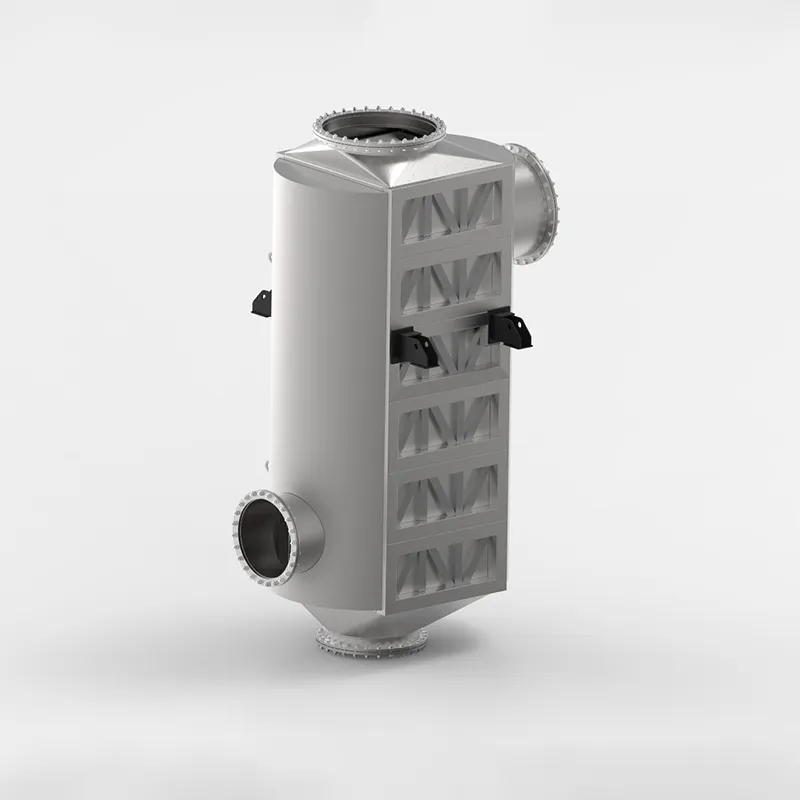
Industrial furnace and boiler exhaust gases carry vast amounts of unutilized thermal energy. The SHPHE custom Plate Air Preheater (PAPH) is target-engineered to intercept this high-temperature flue gas, recovering valuable waste heat and transferring it directly back to incoming combustion air or process gas streams. By substantially elevating the temperature of your flame feed, our custom systems optimize combustion thermodynamics, deliver massive fuel savings, and significantly reduce industrial carbon and emissions footprints. Built to withstand severe flue-gas environments, SHPHE PAPH systems serve as the premier choice for modern, energy-intensive plants prioritizing decarb compliance and maximum thermal efficiency.
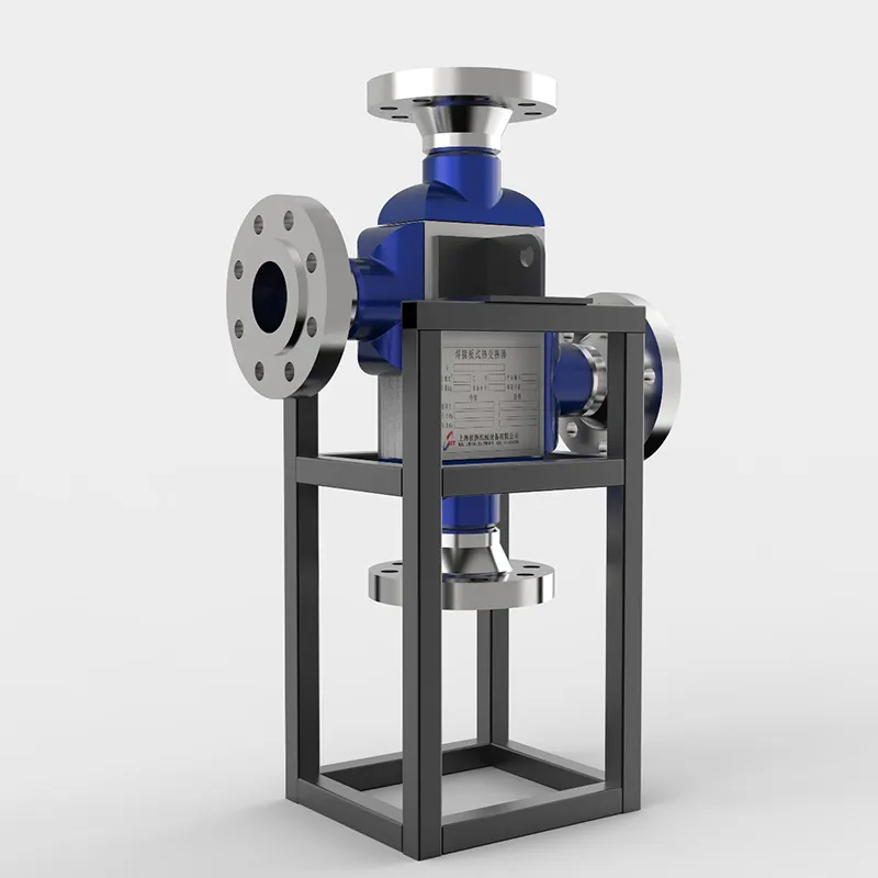
The SHPHE Printed Circuit Heat Exchanger (PCHE) represents a paradigm shift in microchannel thermal management, meticulously engineered for the world's most critical and demanding industrial boundaries. Developed to surpass the physical limitations of conventional shell-and-tube designs in ultra-high-pressure environments, our custom PCHEs integrate advanced photochemical etching and solid-state diffusion bonding to provide unmatched safety, thermal efficiency, and integrity under extreme stress. Initially deployed within high-consequence sectors such as aerospace and nuclear power generation, PCHE technology has completely revolutionized high-density thermal processing. Today, SHPHE brings this breakthrough engineering to mainstream energy transitions—including LNG liquefaction, supercritical CO² power cycles, hydrocarbon processing, and high-pressure hydrogen systems—enabling plants to maximize energy recovery, ensure zero-leakage security, and significantly shrink environmental footprints.
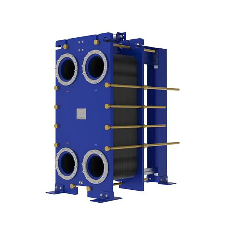
Since the invention of the plate heat exchanger (PHE) in 1923, thermal technology has evolved from standard food-grade processing to highly complex industrial operations. At SHPHE, we take this classic, versatile design and transform it into highly bespoke heat transfer solutions tailored to your unique process fluids and thermal loads. While traditional gasketed PHEs offer high efficiency and compact footprints, SHPHE optimizes plate corrugations, metallurgy, and sealing systems to handle your specific chemical, HVAC, or energy recovery parameters. Our custom-engineered gasketed plate heat exchangers provide outstanding scalability and ease of maintenance, serving as an indispensable asset for heavy industries—including oil and gas, metallurgy, and food processing—where uptime, energy recovery, and long-term sustainability are top priorities.
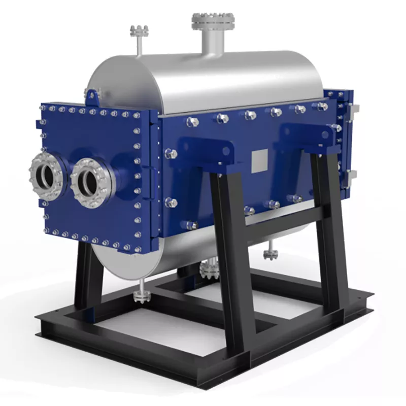
Industrial processes involving particle-laden slurries, high-viscosity syrups, or fiber-rich pulp demand more than standard equipment—they require target-engineered thermal management. At SHPHE, we configure the TP Welded Plate Heat Exchanger to directly conquer your plant's severe fouling, blockage, and erosion threats. Combining custom-tailored channel geometries, wear-resistant metallurgy, and integrated CIP (Cleaning-in-Place) systems, we deliver absolute production continuity where conventional heat exchangers fail.
Select the most popular foreign trade service products to meet your diverse needs
Industrial furnace and boiler exhaust gases carry vast amounts of unutilized thermal energy. The SHPHE custom Plate Air Preheater (PAPH) is target-engineered to intercept this high-temperature flue gas, recovering valuable waste heat and transferring it directly back to incoming combustion air or process gas streams. By substantially elevating the temperature of your flame feed, our custom systems optimize combustion thermodynamics, deliver massive fuel savings, and significantly reduce industrial carbon and emissions footprints. Built to withstand severe flue-gas environments, SHPHE PAPH systems serve as the premier choice for modern, energy-intensive plants prioritizing decarb compliance and maximum thermal efficiency.
Custom-Engineered for Severe Process Demands. At SHPHE, we don't just supply equipment; we design tailored thermal solutions. Our HT-Bloc welded plate heat exchangers are custom-configured by our experienced engineers to overcome your specific industry challenges—whether handling high-viscosity media, extreme temperatures, or strict space constraints.
Since the invention of the plate heat exchanger (PHE) in 1923, thermal technology has evolved from standard food-grade processing to highly complex industrial operations. At SHPHE, we take this classic, versatile design and transform it into highly bespoke heat transfer solutions tailored to your unique process fluids and thermal loads. While traditional gasketed PHEs offer high efficiency and compact footprints, SHPHE optimizes plate corrugations, metallurgy, and sealing systems to handle your specific chemical, HVAC, or energy recovery parameters. Our custom-engineered gasketed plate heat exchangers provide outstanding scalability and ease of maintenance, serving as an indispensable asset for heavy industries—including oil and gas, metallurgy, and food processing—where uptime, energy recovery, and long-term sustainability are top priorities.


User Comments
Service Experience Sharing from Real Customers
maria_lee
Process EngineerWe retrofitted our petrochemical distillation unit with this multipass heat exchanger last quarter, and the thermal efficiency gain is undeniable. The baffle design really minimizes dead zones. Maintenance is a breeze compared to our old single-pass unit. Solid build quality.
tom_b
Facilities ManagerHad to replace a failing chiller bundle in a 20-year-old HVAC system. This multipass exchanger fit the footprint perfectly and dropped our approach temperature by nearly 3°C. Only downside was the lead time was a bit longer than quoted, but the performance makes up for it.
sarah.c
Lead BrewmasterFor our wort chilling stage, consistency is everything. This multipass unit lets me dial in the outlet temp precisely batch after batch. No more hot spots or thermal shock on the yeast. Clean-in-place works a treat too. My brew team loves it.
raj_p
Shift SupervisorIt does the job for our small-scale pharmaceutical reactor cooling, but I wish the documentation included a clearer pressure drop curve for different flow rates. We had to trial-and-error the pump sizing. Works fine now, but the initial setup was more guesswork than I'd like.