Counter Flow vs Parallel Flow Heat Exchanger: Thermal Performance and Design Analysis
Choosing between counter flow vs parallel flow heat exchanger designs directly impacts thermal efficiency, footprint, and operating costs in industrial processes. Counter flow configurations consistently deliver higher log mean temperature difference (LMTD) and require less surface area for the same duty, making them the preferred choice for most oil & gas, chemical, and power generation applications. This article provides a data-driven comparison of thermal performance, pressure drop, and design trade-offs for process engineers and procurement managers evaluating heat exchanger solutions. We also discuss how Shanghai-based SHPHE (founded 2005, ISO9001 and ASME U certified) supports custom designs with free thermal selection services.
What Is the Core Difference Between Counter Flow and Parallel Flow?
In a counter flow heat exchanger, the hot and cold fluids enter from opposite ends and flow in opposite directions. This arrangement maintains a more uniform temperature difference along the entire heat transfer surface. In a parallel flow heat exchanger, both fluids enter from the same end and travel in the same direction, causing the temperature difference to be highest at the inlet and lowest at the outlet.
The practical consequence is clear: counter flow can achieve a closer approach temperature (the difference between the hot fluid outlet and cold fluid outlet), often as low as 2–5 °C, while parallel flow typically limits approach to 10–15 °C. For processes requiring tight temperature control or heat recovery, counter flow is the standard choice.
Thermal Performance: LMTD and Surface Area Comparison
The log mean temperature difference (LMTD) is the driving force for heat transfer. For identical inlet and outlet temperatures, counter flow always yields a higher LMTD than parallel flow. A typical example:
- Hot fluid: 120 °C in → 60 °C out
- Cold fluid: 30 °C in → 80 °C out
- Counter flow LMTD ≈ 35 °C
- Parallel flow LMTD ≈ 22 °C
A higher LMTD means less heat transfer area is required for the same duty. In practice, counter flow designs can reduce surface area by 20–40% compared to parallel flow for the same thermal load. This directly translates to lower capital cost and a smaller equipment footprint.
When Does Parallel Flow Make Sense?
Parallel flow is not without its niche applications. It is often used when the hot fluid contains temperature-sensitive components that could degrade if exposed to very high wall temperatures at the inlet. By having the hottest fluid meet the coldest fluid at the inlet, the wall temperature is moderated. Parallel flow also reduces thermal stress in certain high-temperature applications, such as some waste heat recovery units.
However, for the vast majority of industrial duties — including oil cooling, gas compression intercooling, and chemical reactor temperature control — counter flow is the more efficient and cost-effective arrangement.
Typical Parameter Ranges for Plate Heat Exchangers
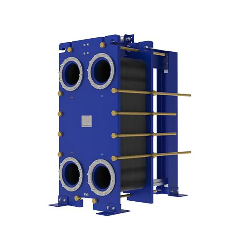
Plate heat exchangers (PHEs) are inherently counter flow devices due to their plate corrugation patterns. Common design parameters include:
| Parameter |
Typical Range |
| Operating pressure |
Up to 30 bar (gasketed), up to 100 bar (welded) |
| Operating temperature |
-40 °C to 400 °C (welded designs) |
| Plate material |
SS304, SS316L, titanium, Hastelloy |
| Heat transfer coefficient |
3,000–7,000 W/m²·K (water-water) |
| Minimum approach temperature |
1–3 °C (counter flow) |
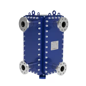
SHPHE offers a full range of plate heat exchangers including gasketed plate heat exchangers for moderate pressures and TP welded plate heat exchangers for high-temperature, high-pressure duties. All designs are optimized for counter flow operation.
How Does Flow Arrangement Affect Pressure Drop?
Pressure drop is a critical factor in pump sizing and energy consumption. Counter flow and parallel flow configurations have similar pressure drop characteristics for the same flow rates and plate geometry. However, because counter flow requires fewer plates for the same duty, the total pressure drop across the heat exchanger is often lower. This means reduced pumping costs over the equipment lifetime.
For viscous fluids or applications with high fouling potential, wide gap designs are recommended. SHPHEs wide gap welded plate heat exchangers handle fibrous slurries and high-viscosity media with minimal clogging while maintaining counter flow efficiency.
Applications and Recommended Solutions
Counter flow heat exchangers are the industry standard for:
- Oil cooling in hydraulic and lubrication systems
- Gas cooling and intercooling in compressors
- Chemical reactor temperature control
- Heat recovery from exhaust gases
- District heating and cooling networks
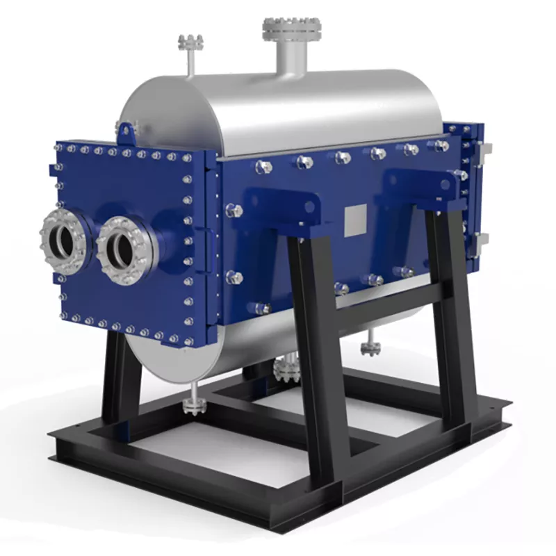
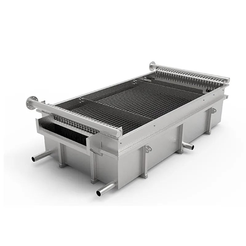
For high-temperature gas-to-gas or gas-to-liquid duties, SHPHEs custom engineered plate air preheaters and HT-Bloc welded plate heat exchangers provide robust counter flow performance with ASME U stamp certification. For compact, high-pressure applications, printed circuit heat exchangers (PCHE) offer extreme efficiency in a small footprint.
Why SHPHE for Your Heat Exchanger Needs?
SHPHE has been manufacturing plate heat exchangers in Shanghai since 2005, exporting to over 20 countries. Our product lines include gasketed, welded, wide gap, PCHE, plate air preheaters, and pillow plates. We hold ISO9001 and ASME U certifications, ensuring every unit meets international quality standards.
Our engineering team provides free thermal design and selection services. We analyze your process conditions — flow rate, temperature, pressure, and media properties — and recommend the optimal counter flow or parallel flow configuration. Our designs are compatible with Alfa Laval, Compabloc, and GEA installations, offering reliable alternatives without compromising performance.
Frequently Asked Questions
Q: Can a parallel flow heat exchanger ever be more efficient than counter flow?
A: No, for the same inlet and outlet temperatures, counter flow always has a higher LMTD and thus higher thermal efficiency. Parallel flow is only chosen when wall temperature moderation is critical to protect sensitive fluids or reduce thermal stress.
Q: What is the typical LMTD correction factor for cross flow vs counter flow?
A: For pure counter flow, the correction factor F = 1.0. For cross flow with both fluids unmixed, F typically ranges from 0.85 to 0.98 depending on temperature approach. For parallel flow, F is always lower than counter flow for the same terminal temperatures.
Q: How do I decide between gasketed and welded plate heat exchangers?
A: Gasketed units are cost-effective for moderate pressures (up to 30 bar) and temperatures (up to 180 °C). Welded designs handle higher pressures (up to 100 bar), higher temperatures (up to 400 °C), and aggressive fluids where gasket compatibility is a concern.
Q: Does SHPHE provide replacement plates for existing heat exchangers?
A: Yes, we manufacture replacement plates compatible with major brands including Alfa Laval, Compabloc, and GEA. We can match existing dimensions, corrugation patterns, and gasket profiles to ensure drop-in fit and performance.
Q: What is the minimum approach temperature achievable with a counter flow plate heat exchanger?
A: With clean fluids and proper design, counter flow plate heat exchangers can achieve approach temperatures as low as 1–3 °C. This makes them ideal for heat recovery applications where maximizing temperature cross is critical.
Q: How does fouling affect the counter flow vs parallel flow comparison?
A: Fouling reduces the effective heat transfer coefficient in both configurations. Counter flow designs are more tolerant because the higher LMTD provides a larger driving force margin. Regular cleaning and proper material selection (e.g., titanium for corrosive media) mitigate fouling effects.
Request a Quote for Your Heat Exchanger Project
Selecting the right flow arrangement — counter flow vs parallel flow — is the first step toward an efficient and cost-effective heat transfer solution. To get a precise thermal design and quotation, please provide the following details:
- Flow rate of each stream (kg/h, m³/h, or GPM)
- Inlet and outlet temperatures (or required duty in kW/BTU)
- Operating pressure and allowable pressure drop
- Media type and composition (including viscosity, density, fouling tendency)
Our team at SHPHE will review your process conditions and recommend the most suitable counter flow or parallel flow heat exchanger design. Contact us today to start your free thermal selection and receive a competitive quote for your project.

 English EN





User Comments
Service Experience Sharing from Real Customers
Mike
Senior Process EngineerI’ve worked with both types over the years, and this counter flow unit is hands down more efficient for our chemical recovery loop. The temperature approach is noticeably tighter—saved us about 8% on steam costs. Parallel flow just can’t match that delta T. Only downside is cleaning the tubes is a bit trickier, but totally worth it.
Sarah
HVAC TechnicianSwapped out an old parallel flow exchanger in a commercial building’s chiller system for this counter flow model. The outlet temps are way more stable now, and the compressor isn’t cycling as hard. Installation was straightforward—no weird flange alignments. I’d give it 5 stars if the manual included a few more troubleshooting tips for air pockets.
Tom
Plant Maintenance SupervisorWe run a dairy pasteurization line and needed better heat recovery. This counter flow exchanger cut our hot water demand by almost 20% compared to the parallel flow we had before. The stainless build handles the milk stone buildup well, and the gaskets are holding up after six months of daily CIP cycles. No leaks yet.
Emma
Junior Design EngineerFor a small lab-scale test rig, I tried a parallel flow unit first because it was cheaper and easier to model. Honestly, the counter flow version I swapped in later performed better for our low-flow, high-temp-difference tests. But the pressure drop was higher than I expected on the cold side—need to factor that in next time. Good for production, maybe overkill for R&D.