How Printed Circuit Heat Exchanger Solves High-Pressure Heat Transfer Challenges
Printed Circuit Heat Exchanger technology ensures safe, efficient, and reliable high-pressure heat transfer with compact design and superior mechanical integrity.
MoreEnsuring that a welded plate satisfies both load-bearing and fatigue requirements in steel structures demands a comprehensive understanding of the types of loads and fatigue regimes that affect welded connections, including static, cyclic, and impact loads. Key design parameters such as plate thickness, weld size, filler material selection, and adherence to welding specifications like AWS D1.1 or ISO 5817 are critical for initial integrity. However, even well-designed welds can fail prematurely if quality control is inadequate; therefore, rigorous inspection methods including ultrasonic testing, magnetic particle inspection, and radiographic examination are essential to detect subsurface flaws that could initiate fatigue cracks. Stress concentration at weld toes and roots remains a primary cause of fatigue failure, necessitating geometric improvements such as smooth weld profiles, grinding, or post-weld heat treatment to redistribute stresses. Finally, fatigue life prediction using finite element analysis (FEA) combined with experimental validation through high-cycle fatigue testing provides a reliable framework to confirm that the welded plate will endure the expected service life without failure. These integrated steps from design through validation are indispensable for achieving safe and durable welded steel structures.
Welded plate connections in steel structures are subjected to various load types that influence fatigue performance. Static loads cause constant stress, while cyclic loads lead to fatigue failure over time. Understanding the load spectrum is essential for ensuring long-term durability.
Fatigue regimes are classified into low-cycle and high-cycle fatigue. Low-cycle fatigue involves high stress amplitudes and fewer cycles, often occurring in seismic or wind-loaded connections. High-cycle fatigue involves lower stress but millions of cycles, typical in bridges and machinery supports.
Key parameters include stress range, mean stress, and notch effects at weld toes. Stress concentration factors must be evaluated using finite element analysis or empirical data. The design must account for tensile residual stresses from welding, which reduce fatigue life.
Standards such as EN 1993-1-9 and AISC 360 provide fatigue categories for welded details. Each category defines permissible stress ranges based on detail geometry and loading direction. Proper classification of the welded joint is the first step in fatigue verification.
For critical applications, a hot-spot stress method or effective notch stress approach is recommended. These methods capture local stress gradients at weld toes more accurately than nominal stress methods. Fatigue testing of representative specimens may also be required for validation.
Load history and frequency must be documented for fatigue assessment. Variable amplitude loading requires cumulative damage models like Miner's rule. The design life should be specified in cycles or years, with appropriate safety factors applied.
Welding process control, post-weld treatment, and inspection also affect fatigue resistance. Techniques such as burr grinding, TIG dressing, or peening can improve fatigue life by reducing stress concentrations and introducing compressive residual stresses.
For further reference on welded plate connections, please visit: Wide Gap Welded Plate Heat Exchanger, TP Welded Plate Heat Exchanger, Gasketed Plate Heat Exchangers, Custom Engineered Pillow Plates, Custom Engineered Plate Air Preheaters, Custom Engineered Printed Circuit Heat Exchanger, and HT Bloc Welded Plate Heat Exchanger.
Load-bearing plates in steel structures must be designed with precise parameters to ensure structural integrity under static and cyclic loading. Critical design factors include plate thickness, base material yield strength, weld joint geometry, and the stress concentration factor at weld toes.
Welding specifications such as electrode classification, preheat temperature, interpass temperature control, and post-weld heat treatment directly influence the fatigue life of the connection. Proper weld profile and penetration depth reduce notch effects and improve load transfer efficiency.
The American Welding Society (AWS) D1.1 code provides comprehensive guidelines for groove weld dimensions, fillet weld sizes, and allowable stress ranges. For plates subjected to high-cycle fatigue, the weld toe should be ground smooth and transition radius should be maximized to reduce stress raisers.
Finite element analysis (FEA) is commonly employed to validate the weld detail against the design fatigue curve. The combination of proper material selection, controlled welding parameters, and non-destructive testing (NDT) ensures the plate meets both ultimate load and fatigue serviceability requirements.
Effective weld quality control is essential to mitigate fatigue failure in steel structures. Fatigue cracks typically initiate at weld toes, roots, or internal discontinuities due to stress concentration. Rigorous inspection protocols ensure that welds meet design specifications and service life expectations.
Key inspection methods include visual examination, ultrasonic testing, magnetic particle inspection, and radiographic testing. Each technique addresses specific defect types such as porosity, lack of fusion, undercut, or slag inclusion. The table below summarizes common weld defects and their impact on fatigue performance.
| Defect Type | Inspection Method | Fatigue Risk | Acceptance Criteria |
|---|---|---|---|
| Porosity | Radiographic Testing (RT) | Moderate | Per AWS D1.1 / ISO 5817 |
| Lack of Fusion | Ultrasonic Testing (UT) | High | Zero tolerance |
| Undercut | Visual Inspection (VT) | Moderate to High | Depth ≤ 0.5 mm |
| Slag Inclusion | Radiographic Testing (RT) | Moderate | Per applicable code |
| Crack | Magnetic Particle (MT) / UT | Very High | Not permitted |
Table 1: Common weld defects, detection methods, and fatigue risk classification. Acceptance criteria should follow relevant structural welding codes such as AWS D1.1 or ISO 5817.
To ensure fatigue resistance, weld profile control is equally important. Smooth transitions, proper reinforcement height, and toe grinding can significantly reduce stress concentration factors. Post-weld treatment methods such as TIG dressing, peening, or ultrasonic impact treatment further improve fatigue life by introducing compressive residual stresses.
For critical applications, a combination of non-destructive testing (NDT) methods is recommended. Ultrasonic testing provides volumetric coverage, while magnetic particle or dye penetrant testing detects surface-breaking defects. Radiographic testing offers a permanent record of internal weld quality. Implementing a structured inspection plan at defined stages—before, during, and after welding—ensures compliance with load and fatigue requirements.
For further reference on welded plate heat exchanger products and related quality standards, visit Wide Gap Welded Plate Heat Exchanger or TP Welded Plate Heat Exchanger.
Stress concentrations at weld toes and roots are primary initiators of fatigue cracks. Optimizing weld geometry reduces local stress raisers, while post-weld treatments introduce compressive residual stresses to extend fatigue life.
Weld Geometry Adjustments: Increasing weld toe radius and reducing flank angle lowers stress concentration factors. Smooth transitions between weld metal and base plate distribute loads more evenly, reducing peak stresses under cyclic loading.
Post-Weld Treatment Methods: Techniques such as grinding, TIG dressing, and hammer peening remove microscopic notches and induce compressive residual stresses. These treatments close crack tips and delay crack initiation, significantly improving fatigue strength.
Quality Control: Regular inspection using dye penetrant or magnetic particle testing ensures treated surfaces are free of defects. Combined with proper weld profiling, these measures achieve reliable performance under high-cycle fatigue conditions.
Fatigue life prediction for welded plates in steel structures requires a combination of numerical simulation and physical testing. Finite Element Analysis (FEA) is employed to identify stress concentration zones and estimate crack initiation points under cyclic loading. The stress-life (S-N) approach or strain-life method is typically applied, depending on the material ductility and loading amplitude. For welded joints, the influence of residual stresses and weld geometry must be incorporated into the FEA model to improve accuracy.
Validation is performed through controlled laboratory fatigue tests using servo-hydraulic actuators. Test specimens are subjected to constant or variable amplitude loading that replicates service conditions. The resulting data, including cycles to failure and crack growth rates, are compared with FEA predictions. Discrepancies are analyzed to refine the model parameters, such as material properties, boundary conditions, and mesh density. This iterative process ensures that the welded plate design meets the required fatigue life criteria.
For further details on welded plate applications and design considerations, refer to relevant product documentation. Wide Gap Welded Plate Heat Exchanger and TP Welded Plate Heat Exchanger provide examples of structural configurations. Additional insights can be found in Gasketed Plate Heat Exchangers and Custom Engineered Pillow Plates. For high-temperature applications, Plate Air Preheaters and Printed Circuit Heat Exchangers offer relevant data. Finally, HT Bloc Welded Plate Heat Exchanger demonstrates advanced fatigue-resistant design.
Ensuring the reliability of welded plates in steel structures under combined load and fatigue demands a systematic approach that integrates load classification, design specifications, and rigorous quality control. A clear understanding of static, cyclic, and impact loads, along with their corresponding fatigue regimes, forms the foundation for safe welded connections.
Key design parameters — including weld size, throat thickness, electrode classification, and preheat requirements — must align with recognized standards such as AWS D1.1 or Eurocode 3. These specifications directly influence the load-bearing capacity and fatigue resistance of the joint.
Weld quality control, through non-destructive testing (ultrasonic, magnetic particle, or radiographic inspection), is essential to detect subsurface discontinuities that could initiate fatigue cracks. Combined with strict acceptance criteria, these methods significantly reduce the probability of premature failure.
Mitigating stress concentration at the weld toe and root — via optimized weld profiling, grinding, TIG dressing, or peening — enhances the fatigue life of the connection. Post-weld heat treatment may further relieve residual tensile stresses in critical applications.
Finally, fatigue life prediction using finite element analysis (FEA) combined with experimental S-N data or strain-life methods provides a validated framework for assessing long-term performance. Correlation between numerical models and physical testing ensures that the welded plate meets both load and fatigue requirements throughout its intended service life.
This summary consolidates the critical aspects of welded plate design, fabrication, inspection, and validation for fatigue-resistant steel structures.
We provide you with comprehensive foreign trade solutions to help enterprises achieve global development
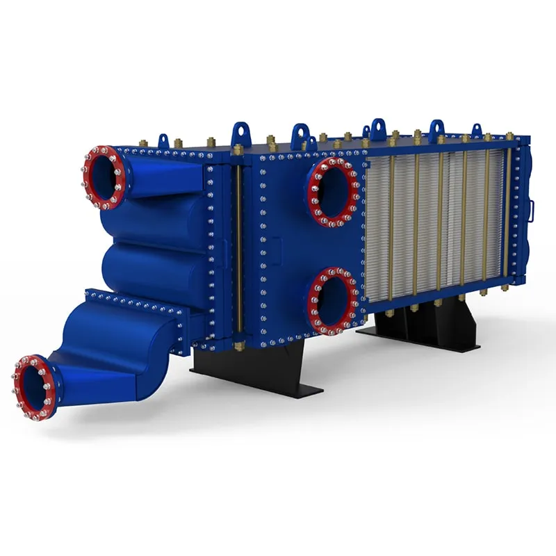
Custom-Engineered for Severe Process Demands. At SHPHE, we don't just supply equipment; we design tailored thermal solutions. Our HT-Bloc welded plate heat exchangers are custom-configured by our experienced engineers to overcome your specific industry challenges—whether handling high-viscosity media, extreme temperatures, or strict space constraints.
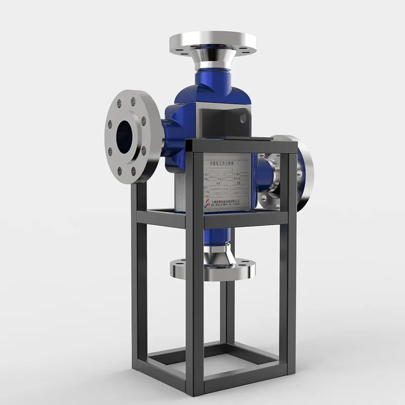
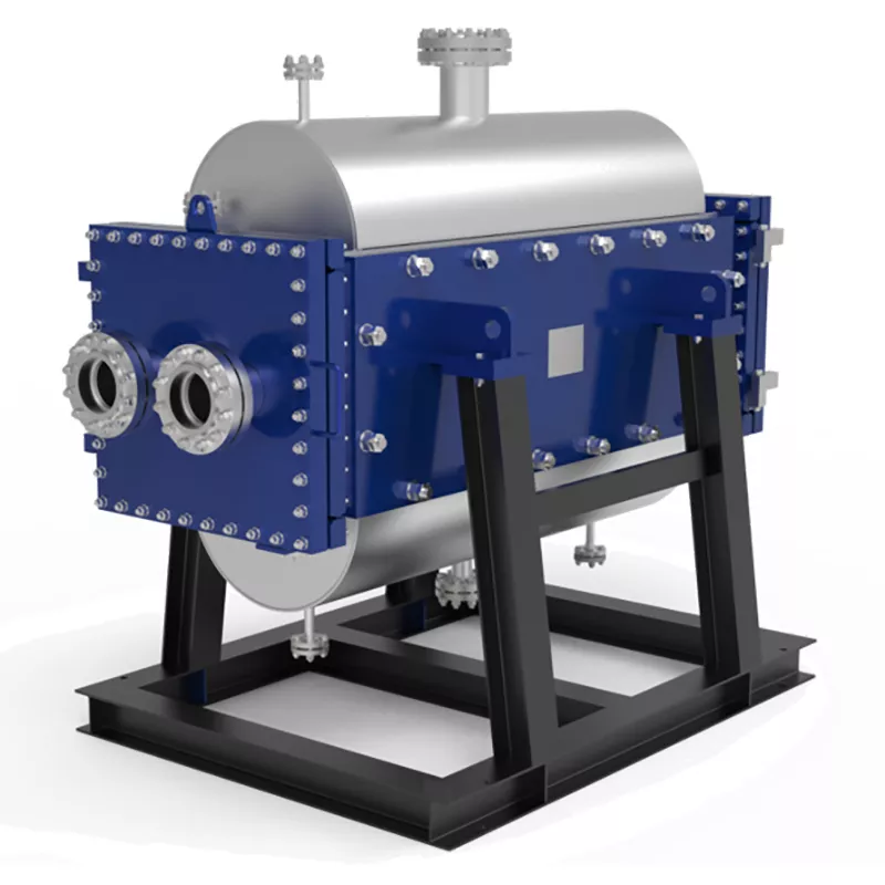
The SHPHE Printed Circuit Heat Exchanger (PCHE) represents a paradigm shift in microchannel thermal management, meticulously engineered for the world's most critical and demanding industrial boundaries. Developed to surpass the physical limitations of conventional shell-and-tube designs in ultra-high-pressure environments, our custom PCHEs integrate advanced photochemical etching and solid-state diffusion bonding to provide unmatched safety, thermal efficiency, and integrity under extreme stress. Initially deployed within high-consequence sectors such as aerospace and nuclear power generation, PCHE technology has completely revolutionized high-density thermal processing. Today, SHPHE brings this breakthrough engineering to mainstream energy transitions—including LNG liquefaction, supercritical CO² power cycles, hydrocarbon processing, and high-pressure hydrogen systems—enabling plants to maximize energy recovery, ensure zero-leakage security, and significantly shrink environmental footprints.
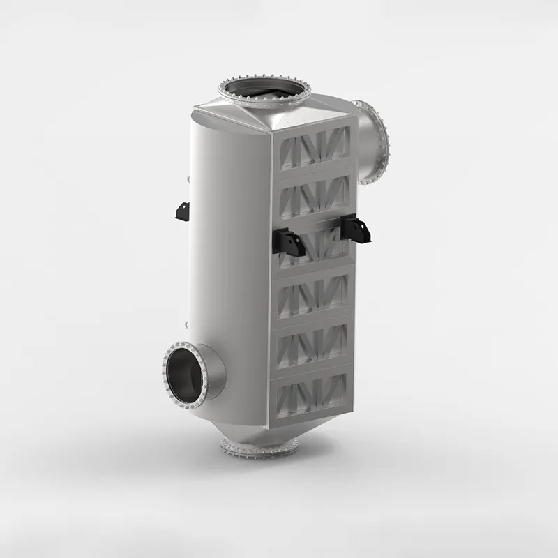
Industrial furnace and boiler exhaust gases carry vast amounts of unutilized thermal energy. The SHPHE custom Plate Air Preheater (PAPH) is target-engineered to intercept this high-temperature flue gas, recovering valuable waste heat and transferring it directly back to incoming combustion air or process gas streams. By substantially elevating the temperature of your flame feed, our custom systems optimize combustion thermodynamics, deliver massive fuel savings, and significantly reduce industrial carbon and emissions footprints. Built to withstand severe flue-gas environments, SHPHE PAPH systems serve as the premier choice for modern, energy-intensive plants prioritizing decarb compliance and maximum thermal efficiency.
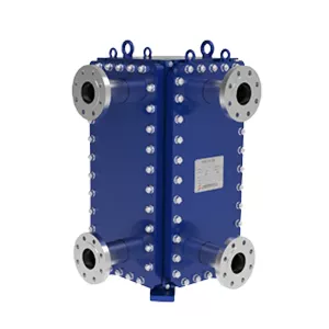
Industrial processes involving particle-laden slurries, high-viscosity syrups, or fiber-rich pulp demand more than standard equipment—they require target-engineered thermal management. At SHPHE, we configure the TP Welded Plate Heat Exchanger to directly conquer your plant's severe fouling, blockage, and erosion threats. Combining custom-tailored channel geometries, wear-resistant metallurgy, and integrated CIP (Cleaning-in-Place) systems, we deliver absolute production continuity where conventional heat exchangers fail.
Select the most popular foreign trade service products to meet your diverse needs
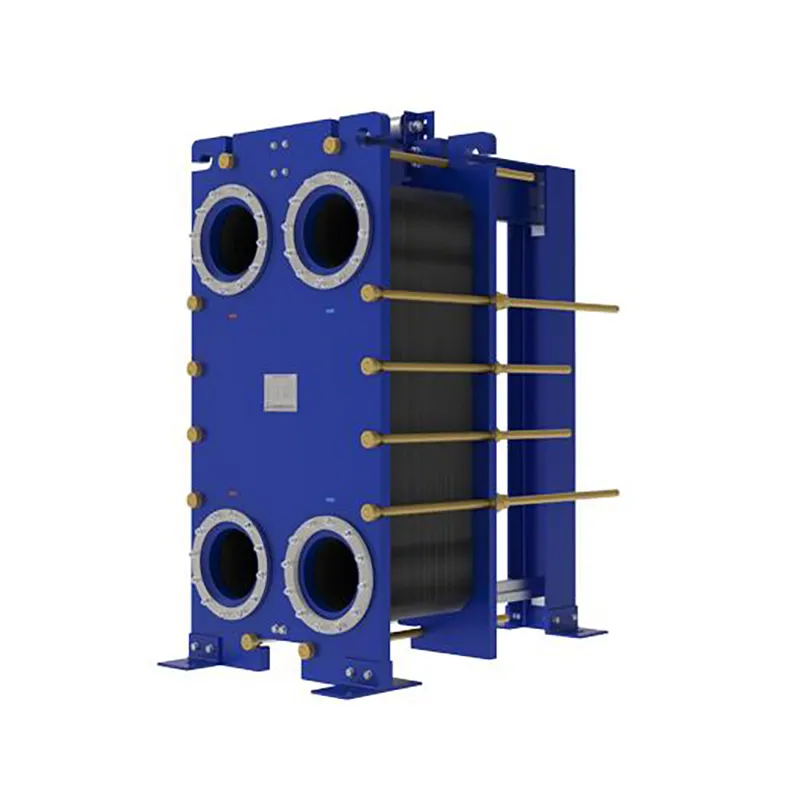
Since the invention of the plate heat exchanger (PHE) in 1923, thermal technology has evolved from standard food-grade processing to highly complex industrial operations. At SHPHE, we take this classic, versatile design and transform it into highly bespoke heat transfer solutions tailored to your unique process fluids and thermal loads. While traditional gasketed PHEs offer high efficiency and compact footprints, SHPHE optimizes plate corrugations, metallurgy, and sealing systems to handle your specific chemical, HVAC, or energy recovery parameters. Our custom-engineered gasketed plate heat exchangers provide outstanding scalability and ease of maintenance, serving as an indispensable asset for heavy industries—including oil and gas, metallurgy, and food processing—where uptime, energy recovery, and long-term sustainability are top priorities.
Industrial furnace and boiler exhaust gases carry vast amounts of unutilized thermal energy. The SHPHE custom Plate Air Preheater (PAPH) is target-engineered to intercept this high-temperature flue gas, recovering valuable waste heat and transferring it directly back to incoming combustion air or process gas streams. By substantially elevating the temperature of your flame feed, our custom systems optimize combustion thermodynamics, deliver massive fuel savings, and significantly reduce industrial carbon and emissions footprints. Built to withstand severe flue-gas environments, SHPHE PAPH systems serve as the premier choice for modern, energy-intensive plants prioritizing decarb compliance and maximum thermal efficiency.
Custom-Engineered Anti-Clogging Solutions for High-Viscosity Slurries: Deployed specifically to conquer severe industrial fouling, SHPHE wide gap welded plate heat exchangers are tailor-built to handle complex media containing dense fibers, coarse crystals, or solid suspensions without clogging. Each non-obstructed channel is calculated and formed by laser-welded plate packs matching your fluid’s exact rheology and grain size, completely eliminating structural "dead zones" and media stagnation. Available in highly compact vertical and versatile horizontal configurations, our vertical engineering drastically reduces plant footprints while maintaining unhindered product throughput, minimal pressure drops, and flawless continuous operations across harsh process loops.


User Comments
Service Experience Sharing from Real Customers
Marcus
Structural WelderI’ve been using these welded plates for a bridge retrofit project. The consistency in the weld penetration is impressive—no slag inclusions or weak spots. Saved me a ton of rework time on site.
Elena
Mechanical EngineerOrdered a batch for a custom pressure vessel. The dimensional tolerance was spot on, and the plate surface prep made it easy to inspect. Only wish the edge finish was a bit cleaner for high-cycle fatigue applications.
Tommy
Maintenance SupervisorWe’ve been replacing worn-out parts in our grain silo system. These welded plates hold up well under heavy vibration and dust. No cracking after six months of continuous use—definitely a solid buy.
Priya
QA InspectorChecked a sample from our latest shipment with ultrasonic testing. The weld quality was uniform, and the heat-affected zone was narrower than I expected. Good for structural applications where you need reliable load transfer.