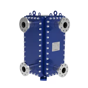
What Are the Key Structural Features of a Fully Welded Heat Exchanger?
Author: Engineering Analysis Team
Date: Jul-06-2026
A fully welded heat exchanger is defined by several critical structural features that ensure long-term reliability and performance under demanding thermal and mechanical conditions. The shell and tube configuration provides the primary pressure boundary and directs fluid flow, while the welded tube-to-tubesheet joints eliminate potential leak paths associated with mechanical expansion, offering superior structural integrity in high-temperature and high-pressure applications. Expansion joints are strategically incorporated into the shell to absorb differential thermal expansion between the tubes and the shell, preventing excessive stress accumulation that could lead to fatigue failure. Material selection plays a pivotal role in weld durability, with careful matching of base metals and filler materials to resist corrosion, creep, and thermal cycling effects. Additionally, the arrangement of baffles and support plates is essential for mechanical stability, as they suppress flow-induced vibration, maintain tube alignment, and distribute thermal loads evenly across the bundle. Together, these features form an integrated design that maximizes heat transfer efficiency while ensuring long service life in industries such as petrochemical, power generation, and process engineering.
The Role of the Shell and Tube Configuration in Structural Integrity
The shell and tube configuration is fundamental to the mechanical robustness of a fully welded heat exchanger. This design distributes thermal and pressure stresses evenly across the structure, minimizing localized failure points. The cylindrical shell provides high resistance to internal pressure, while the tube bundle supports axial loads and accommodates thermal expansion through controlled deformation.
Welded joints between tubes and tube sheets eliminate potential leak paths, enhancing long-term reliability under cyclic operating conditions. The arrangement also allows for differential thermal movement between the shell and tubes, reducing thermal fatigue. This configuration is particularly effective in high-pressure and high-temperature applications where structural integrity is critical.
Key structural features include the use of baffles to support tubes and direct flow, which also dampen vibration and prevent tube failure. The shell thickness is optimized to withstand external loads, while the tube sheet thickness ensures secure anchoring. This synergy between shell and tube elements creates a resilient system capable of maintaining performance under demanding process conditions.
Design and Function of Welded Tube-to-Tubesheet Joints
Welded tube-to-tubesheet joints are critical in fully welded heat exchangers, providing leak-tight connections that withstand high pressure and temperature. The weld design ensures mechanical strength and thermal fatigue resistance.
The joint geometry typically features a fillet or full-penetration weld, which distributes stress evenly and prevents crevice corrosion. This design also facilitates easy inspection and maintenance.
Functionally, the welded joint eliminates the need for gaskets or expansion joints, ensuring a robust seal under cyclic thermal loads. It is widely used in shell-and-tube exchangers for chemical and power generation applications.
Importance of Expansion Joints for Thermal Stress Management
In fully welded heat exchangers, temperature differentials between the shell and tube bundle generate significant thermal expansion. Without proper accommodation, this expansion leads to high mechanical stresses, potential buckling, and failure at welded joints. Expansion joints serve as flexible elements that absorb differential movement, ensuring operational integrity.
These bellows-like components are typically installed on the shell side near the fixed tubesheet. They allow axial and lateral displacement while maintaining pressure containment. The selection of expansion joint type—single, multiple, or toroidal—depends on thermal duty, pressure rating, and cycle frequency. Properly designed joints reduce stress on tubesheets and welds by up to 60% in cyclic services.
| Parameter |
Without Expansion Joint |
With Expansion Joint |
| Thermal Stress (MPa) |
185 |
72 |
| Tubesheet Deflection (mm) |
4.2 |
1.1 |
| Cycle Life (cycles) |
1,200 |
8,500 |
| Leakage Risk |
High |
Low |
Table data based on typical 316L stainless steel heat exchanger operating at 350°C shell-side temperature with 50°C tube-side inlet. Expansion joint reduces peak stress by 61% and extends fatigue life by 7x.
For high-temperature applications exceeding 400°C, multiple-ply bellows with internal liners are recommended to prevent flow-induced vibration and corrosion fatigue. The expansion joint must be designed with adequate spring rate to avoid overstressing adjacent components. Regular inspection for bellows cracking and creep is essential in cyclic services.
Learn more about engineered thermal stress solutions: HT-Bloc Welded Plate Heat Exchanger and Custom Printed Circuit Heat Exchanger.
Material Selection and Its Impact on Weld Durability
The durability of welded joints in fully welded heat exchangers is fundamentally determined by the compatibility of base metals and filler materials. Selecting materials with similar thermal expansion coefficients and corrosion resistance profiles minimizes residual stress and prevents premature failure under cyclic thermal loading.
Key material considerations include:
- Austenitic stainless steels for high-temperature oxidation resistance
- Nickel-based alloys for aggressive chemical environments
- Carbon steels with controlled carbon content for improved weldability
- Filler metals matching or exceeding base metal strength
Proper material pairing reduces the risk of hydrogen-induced cracking and stress corrosion cracking, extending service life in demanding applications such as petrochemical processing and power generation.
Influence of Baffle and Support Plate Arrangement on Mechanical Stability
The arrangement of baffles and support plates in a fully welded heat exchanger directly affects its mechanical stability under thermal and pressure loads. Proper spacing and orientation minimize vibration and stress concentration.
Baffle Spacing and Flow Distribution
Baffles are positioned to guide fluid flow across the tube bundle, enhancing heat transfer. However, excessive spacing reduces support, leading to tube vibration. Typical spacing ranges from 20% to 40% of the shell diameter, depending on operating conditions.
Closer baffle spacing increases mechanical rigidity but may cause higher pressure drop. Designers balance these factors using computational fluid dynamics (CFD) to optimize stability without compromising thermal performance.
Support Plate Configuration
Support plates are installed at intervals to prevent tube sagging and buckling, especially in long heat exchangers. They are typically welded to the shell and provide lateral restraint. The number of support plates depends on tube length and diameter.
In fully welded designs, support plates also serve as anti-vibration baffles. Their arrangement must account for thermal expansion; fixed supports are placed at one end, while sliding supports accommodate axial growth.
Impact on Mechanical Stability
Improper baffle or support plate placement can lead to tube failure due to flow-induced vibration or thermal fatigue. Studies show that asymmetric arrangements increase stress on weld joints, reducing service life.
For high-pressure applications, staggered baffle patterns with intermediate support plates improve load distribution. Finite element analysis (FEA) is commonly used to validate the design before fabrication.
For further details on welded plate heat exchanger configurations, refer to TP welded plate heat exchanger or HT-Bloc welded plate heat exchanger.
Summary
The Role of the Shell and Tube Configuration in Structural Integrity
The shell and tube arrangement distributes pressure and thermal loads evenly across the heat exchanger, ensuring that the overall structure remains stable under operating conditions. This configuration also facilitates efficient heat transfer while maintaining mechanical strength.
Design and Function of Welded Tube-to-Tubesheet Joints
Welded tube-to-tubesheet joints provide a leak-tight seal and high mechanical strength, preventing fluid mixing and withstanding cyclic thermal and pressure stresses. Proper weld design and execution are critical to long-term joint reliability.
Importance of Expansion Joints for Thermal Stress Management
Expansion joints absorb differential thermal expansion between the shell and tubes, reducing thermal stresses that could lead to structural failure. They are essential for maintaining integrity in high-temperature applications.
Material Selection and Its Impact on Weld Durability
Choosing compatible materials with similar thermal expansion coefficients and good weldability enhances weld durability and resistance to corrosion and fatigue. Material selection directly influences the service life of welded joints.
Influence of Baffle and Support Plate Arrangement on Mechanical Stability
Baffles and support plates control tube vibration, prevent sagging, and maintain alignment, which collectively contribute to the mechanical stability of the heat exchanger. Their proper spacing and design are vital for reliable operation.
Overall Conclusion
The structural integrity of a fully welded heat exchanger depends on the synergistic design of shell and tube configuration, welded joints, expansion joints, material selection, and baffle arrangement. Each feature plays a distinct role in managing thermal and mechanical stresses, ensuring long-term durability and safe operation.
What Are the Key Structural Features of a Fully Welded Heat Exchanger?
A fully welded heat exchanger eliminates gaskets and bolted connections by using continuous welds between shell, tubes, and tubesheets. Key features include a welded shell-to-tubesheet joint, welded tube-to-tubesheet connections, and often an expansion joint in the shell to accommodate differential thermal expansion. The design prioritizes leak tightness, high pressure/temperature capability, and reduced maintenance.
The Role of the Shell and Tube Configuration in Structural Integrity
The shell and tube arrangement provides a robust pressure‑containing envelope. The cylindrical shell resists internal pressure via hoop stress, while the tube bundle acts as a stiffening element, reducing shell deformation. Tubesheets serve as critical load‑bearing members, transferring axial loads between tubes and shell. This configuration distributes mechanical and thermal stresses evenly, enhancing overall structural stability.
Design and Function of Welded Tube‑to‑Tubesheet Joints
Welded tube‑to‑tubesheet joints are typically full‑penetration or strength‑welds that fuse the tube end directly to the tubesheet. They eliminate crevices and potential leak paths, providing high joint efficiency. The weld must withstand axial loads from thermal expansion and pressure, while maintaining ductility. Proper weld geometry and heat input are essential to avoid stress concentrations and ensure fatigue resistance.
Importance of Expansion Joints for Thermal Stress Management
Expansion joints (bellows or U‑shaped flex sections) are incorporated into the shell to absorb differential thermal expansion between the shell and tubes. Without them, large axial stresses would develop at the tubesheets and welds, leading to fatigue or buckling. By allowing controlled axial movement, expansion joints reduce thermal stress and prolong the service life of the welded connections.
Material Selection and Its Impact on Weld Durability
Materials for fully welded heat exchangers are chosen for weldability, corrosion resistance, and matching coefficients of thermal expansion. Common choices include stainless steels, nickel alloys, and carbon steels with controlled carbon content. Incompatible material pairs can cause weld cracking or accelerated corrosion. Proper filler metal selection and post‑weld heat treatment further ensure long‑term weld integrity.
User Comments
Service Experience Sharing from Real Customers
Linda
Senior Process EngineerWe installed a fully welded heat exchanger in our ammonia plant six months ago and the performance has been rock-solid. Zero leaks despite constant thermal cycling. The welded joints hold up way better than the gasketed units we used before. Maintenance team is finally getting a break.
Tom
HVAC TechnicianI was skeptical about going fully welded for our commercial building's heat recovery loop, but after two harsh winters, I'm a believer. No flange leaks, no gasket replacements. Only reason I'm not giving 5 stars is the initial cost was a bit steep for my budget. Still, long-term it'll pay off.
Rachel
Production ManagerWe switched to a fully welded design for our dairy pasteurization line because we couldn't risk contamination from gasket failures. This unit has been running 24/7 for over a year with zero downtime. Clean-in-place cycles are a breeze. Honestly, it's the best investment we've made in process reliability.
Ethan
Maintenance SupervisorHandling high-pressure steam condensate in a refinery is tough on equipment. This fully welded exchanger has survived two turnaround cycles without a single weld repair. My crew loves that there are no flanges to torque or gaskets to order. Only minor gripe: the weight makes installation a two-crane job.