How Printed Circuit Heat Exchanger Solves High-Pressure Heat Transfer Challenges
Printed Circuit Heat Exchanger technology ensures safe, efficient, and reliable high-pressure heat transfer with compact design and superior mechanical integrity.
MoreDr. Elena V. Morrison, Prof. Kenji T. Harada
Jun-09-2026
Asymmetric plate channel geometry represents a significant advancement in shell and plate heat exchanger design. By intentionally varying the channel cross-section along the flow path, engineers can manipulate fluid velocity profiles to achieve more uniform heat transfer across the entire plate surface. This design approach directly addresses the common issue of maldistribution, where stagnant zones or high-velocity streaks reduce overall thermal effectiveness.
The asymmetric configuration typically features a gradual expansion or contraction in one direction, creating a controlled pressure gradient that forces fluid to redistribute more evenly. Computational fluid dynamics studies demonstrate that such channel shaping can reduce temperature non-uniformity by up to 40% compared to symmetric parallel plate designs. This improvement is particularly valuable in applications involving viscous fluids or those with temperature-sensitive properties.
Key parameters influencing the effect include the aspect ratio of the channel, the angle of asymmetry, and the Reynolds number of the flow. When properly optimized, asymmetric channels promote secondary flows that enhance mixing near the walls, thereby increasing local heat transfer coefficients. The result is a more consistent thermal performance across the heat exchanger, reducing the risk of hot spots and improving overall energy efficiency.
For further technical insights into plate heat exchanger design, visit custom engineered plate air preheaters or explore gasketed plate heat exchangers for additional case studies on flow optimization.
The practical implementation of asymmetric channels requires careful consideration of manufacturing tolerances and plate material properties. However, the thermal performance gains often justify the additional design complexity, particularly in high-performance industrial applications where even small improvements in heat transfer uniformity translate into significant energy savings and extended equipment lifespan.
Chevron corrugations and specialized surface patterns on shell & plate heat exchanger plates create complex flow paths that disrupt laminar boundary layers. This induced turbulence increases convective heat transfer coefficients significantly, often improving thermal performance by 20-40% compared to smooth plates, while maintaining manageable pressure drops.
The chevron angle and pattern depth are optimized to generate eddies and secondary flows that sweep heat from the plate surface. These geometric features also increase effective surface area and promote fluid mixing, directly enhancing the overall heat transfer coefficient (U-value) in both single-phase and two-phase applications.
Shell & plate heat exchangers utilize a compact shell-side geometry that differs significantly from conventional shell-and-tube designs. The narrow, corrugated flow channels on the shell side create controlled turbulence, which enhances heat transfer without the excessive resistance seen in traditional baffled shells. This geometry reduces the cross-sectional flow area gradually, maintaining velocity and promoting efficient thermal exchange across the plate pack.
The elimination of large baffle structures and the use of optimized plate spacing allow the fluid to follow a smooth, uninterrupted path. This results in a lower overall pressure drop compared to conventional designs, while the high surface-area-to-volume ratio of the plates ensures that heat transfer coefficients remain elevated. The compact arrangement also minimizes dead zones and recirculation areas, further contributing to consistent thermal performance.
The table below summarizes typical performance comparisons between compact shell-side geometry and traditional shell-and-tube arrangements under similar operating conditions.
| Parameter | Compact Shell-Side Geometry | Traditional Shell-and-Tube |
|---|---|---|
| Heat Transfer Coefficient (W/m²·K) | 3500 – 5500 | 1500 – 3000 |
| Pressure Drop (kPa) | 20 – 50 | 40 – 100 |
| Surface Area Density (m²/m³) | 200 – 500 | 80 – 200 |
| Typical Flow Regime | Turbulent / Transitional | Laminar / Transitional |
As shown in the data, the compact shell-side geometry achieves significantly higher heat transfer coefficients while operating at a lower pressure drop range. The increased surface area density directly contributes to the thermal improvement, making these exchangers ideal for applications where space and energy efficiency are critical. For further technical details on similar engineered plate solutions, please refer to custom pillow plates or TP welded plate heat exchangers.
The design also facilitates easier cleaning and maintenance due to the accessible plate surfaces, while the reduced pressure drop lowers pumping costs over the equipment lifecycle. Additional resources on advanced plate heat exchanger configurations can be found through wide gap welded plate units and HT Bloc welded plate exchangers.
The thermal performance and operational reliability of shell and plate heat exchangers are fundamentally governed by material selection and weld quality. Choosing the right base metals and filler materials directly impacts thermal conductivity, while robust weld integrity ensures leak-free operation under high pressure and temperature cycles.
High-conductivity materials such as stainless steel 316L, titanium, and nickel alloys are commonly specified for plate packs. These materials offer superior heat transfer coefficients, reducing thermal resistance between fluids. The selection must also consider corrosion resistance and fouling characteristics, as material degradation over time can diminish thermal performance and lead to premature failure.
In shell and plate heat exchangers, welded joints between plates and between the plate pack and shell must be free from porosity, cracks, and incomplete fusion. Advanced welding techniques like laser welding and orbital TIG welding ensure deep penetration and minimal heat-affected zones. Proper weld design prevents intergranular corrosion and fatigue cracking, which are common sources of inter-fluid leakage in high-stress thermal cycling environments.
When materials with high thermal conductivity are paired with defect-free welds, the heat exchanger achieves lower approach temperatures and higher overall heat transfer coefficients. Simultaneously, weld integrity eliminates bypass leakage, ensuring that the full flow participates in heat exchange. This synergy between material science and fabrication quality is essential for maximizing energy efficiency and extending equipment service life in demanding industrial applications.
The thermal performance of a shell & plate heat exchanger is fundamentally governed by the temperature driving force, quantified as the Log Mean Temperature Difference (LMTD). Two critical design features—countercurrent flow arrangement and multi-pass configurations—directly enhance this parameter, leading to superior heat transfer rates without increasing the surface area.
In a countercurrent flow arrangement, the hot and cold fluids enter the exchanger from opposite ends and flow in opposing directions. This configuration maintains a more uniform and higher temperature difference across the entire heat transfer surface compared to parallel flow. Mathematically, the LMTD for countercurrent flow is always greater than or equal to that for parallel flow under the same inlet and outlet temperature conditions. For example, when the temperature change of one fluid is large, the countercurrent LMTD can be significantly higher, enabling the exchanger to achieve closer approach temperatures (the difference between the hot fluid outlet and cold fluid inlet). This feature is especially beneficial in applications requiring high thermal efficiency, such as in custom-engineered plate air preheaters.
Multi-pass configurations further optimize the LMTD by routing one or both fluids through the exchanger multiple times. In a shell & plate heat exchanger, a multi-pass design on the plate side (e.g., 2-pass or 4-pass) forces the fluid to traverse the core multiple times, effectively increasing the flow path length and the temperature gradient. While multi-pass arrangements introduce some crossflow or mixed-flow zones, the overall effective LMTD is often higher than a single-pass arrangement when the temperature cross is significant. For instance, in TP welded plate heat exchangers, multi-pass designs are employed to handle large temperature differences and to maximize heat recovery. The correction factor for LMTD in multi-pass configurations must be carefully calculated using standard charts or equations, but the net result is a more compact exchanger for a given duty.
When countercurrent flow is combined with a multi-pass plate arrangement, the thermal performance is maximized. The countercurrent arrangement ensures the highest possible LMTD for the overall temperature profile, while the multi-pass design allows for better utilization of the available surface area by increasing the fluid velocity and turbulence. This synergy is particularly evident in high-performance units like HT Bloc welded plate heat exchangers, where both features are integral to achieving high heat transfer coefficients and compact footprints. The result is a reduction in the required heat transfer area by up to 20-30% compared to a simple single-pass parallel flow design, directly lowering capital costs and space requirements.
Engineers must evaluate the LMTD correction factor (F) for multi-pass and non-pure countercurrent flows. While a pure countercurrent flow has an F factor of 1.0, multi-pass configurations typically have F values between 0.8 and 0.98. The goal is to design the flow arrangement such that the F factor remains above 0.75 to avoid thermodynamic inefficiency. Advanced shell & plate designs, such as those found in custom-engineered pillow plates or wide gap welded plate heat exchangers, utilize computational fluid dynamics (CFD) to optimize the flow paths, ensuring that the countercurrent and multi-pass features are balanced to deliver the maximum LMTD for the specific process conditions.
Summary
The shell & plate heat exchanger achieves superior thermal performance through a combination of design innovations. Asymmetric plate channels optimize flow distribution, ensuring uniform heat transfer across the entire surface. Chevron and other surface patterns enhance turbulence generation, disrupting boundary layers and increasing convective heat transfer coefficients. The compact shell-side geometry effectively reduces pressure drop while maintaining high heat transfer rates, balancing efficiency with operational cost.
Material selection and weld integrity are critical for maximizing thermal conductivity and preventing leaks, directly impacting long-term reliability and performance. Furthermore, the countercurrent flow arrangement, along with multi-pass configurations, significantly elevates the log mean temperature difference (LMTD), driving greater heat exchange effectiveness. Collectively, these features make the shell & plate heat exchanger a highly efficient, durable, and compact solution for demanding thermal management applications.
We provide you with comprehensive foreign trade solutions to help enterprises achieve global development
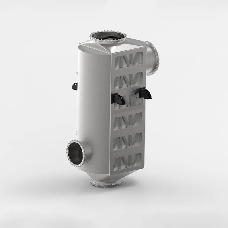
Industrial furnace and boiler exhaust gases carry vast amounts of unutilized thermal energy. The SHPHE custom Plate Air Preheater (PAPH) is target-engineered to intercept this high-temperature flue gas, recovering valuable waste heat and transferring it directly back to incoming combustion air or process gas streams. By substantially elevating the temperature of your flame feed, our custom systems optimize combustion thermodynamics, deliver massive fuel savings, and significantly reduce industrial carbon and emissions footprints. Built to withstand severe flue-gas environments, SHPHE PAPH systems serve as the premier choice for modern, energy-intensive plants prioritizing decarb compliance and maximum thermal efficiency.
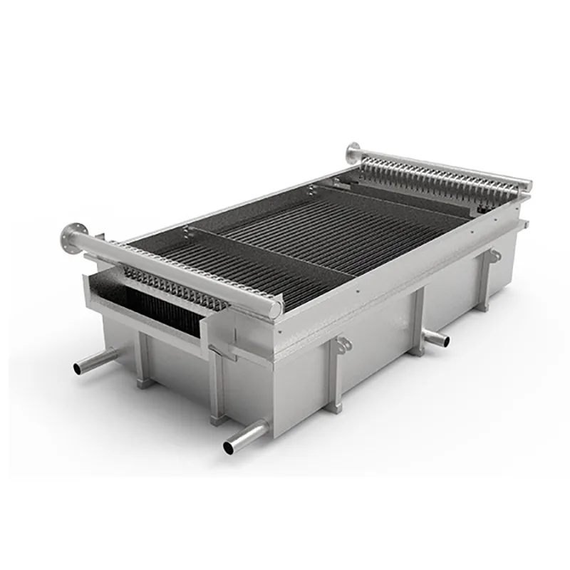
Originated in the mid-20th century to bypass the manufacturing bottlenecks and weight limitations of standard jacketed thermal components, the Pillow Plate (also known as a dimple plate or embossed plate) has revolutionized precision fluid-wall engineering. At SHPHE, we take this highly flexible technology and elevate it into a core foundation for bespoke industrial heat transfer integration. By utilizing state-of-the-art automated CNC fiber laser welding, our engineers customize the mechanical inflation profiles and spot pitch grids to directly match your specific fluid dynamics, pressure limits, and vessel configurations. Today, SHPHE's custom pillow plates are indispensable assets for worldwide processing plants prioritizing advanced thermal performance, zero-leak safety, and hygienic processing—serving as the definitive solution across food, pharmaceutical, chemical, and bulk solids cooling sectors.
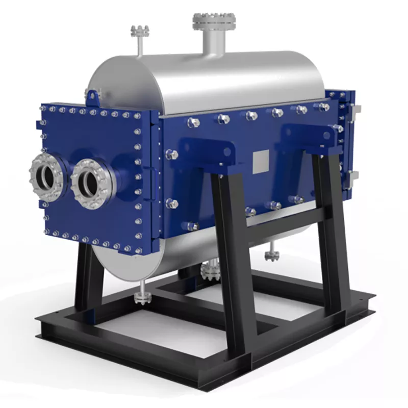
Industrial processes involving particle-laden slurries, high-viscosity syrups, or fiber-rich pulp demand more than standard equipment—they require target-engineered thermal management. At SHPHE, we configure the TP Welded Plate Heat Exchanger to directly conquer your plant's severe fouling, blockage, and erosion threats. Combining custom-tailored channel geometries, wear-resistant metallurgy, and integrated CIP (Cleaning-in-Place) systems, we deliver absolute production continuity where conventional heat exchangers fail.
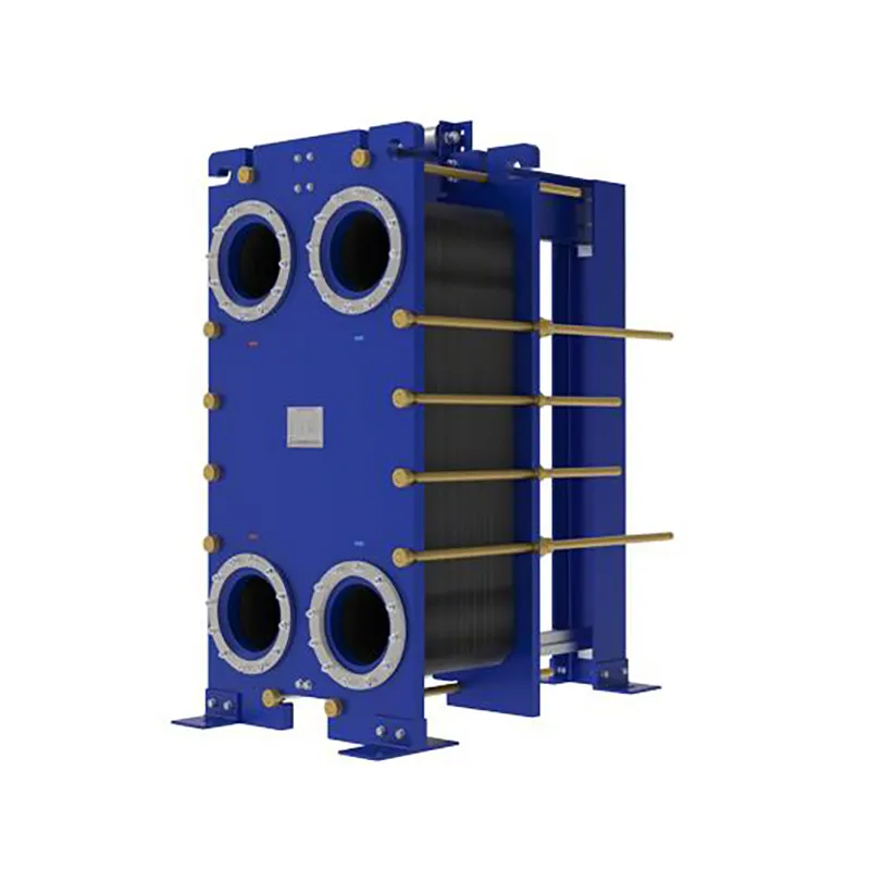
Since the invention of the plate heat exchanger (PHE) in 1923, thermal technology has evolved from standard food-grade processing to highly complex industrial operations. At SHPHE, we take this classic, versatile design and transform it into highly bespoke heat transfer solutions tailored to your unique process fluids and thermal loads. While traditional gasketed PHEs offer high efficiency and compact footprints, SHPHE optimizes plate corrugations, metallurgy, and sealing systems to handle your specific chemical, HVAC, or energy recovery parameters. Our custom-engineered gasketed plate heat exchangers provide outstanding scalability and ease of maintenance, serving as an indispensable asset for heavy industries—including oil and gas, metallurgy, and food processing—where uptime, energy recovery, and long-term sustainability are top priorities.
Select the most popular foreign trade service products to meet your diverse needs
Industrial processes involving particle-laden slurries, high-viscosity syrups, or fiber-rich pulp demand more than standard equipment—they require target-engineered thermal management. At SHPHE, we configure the TP Welded Plate Heat Exchanger to directly conquer your plant's severe fouling, blockage, and erosion threats. Combining custom-tailored channel geometries, wear-resistant metallurgy, and integrated CIP (Cleaning-in-Place) systems, we deliver absolute production continuity where conventional heat exchangers fail.
Custom-Engineered Anti-Clogging Solutions for High-Viscosity Slurries: Deployed specifically to conquer severe industrial fouling, SHPHE wide gap welded plate heat exchangers are tailor-built to handle complex media containing dense fibers, coarse crystals, or solid suspensions without clogging. Each non-obstructed channel is calculated and formed by laser-welded plate packs matching your fluid’s exact rheology and grain size, completely eliminating structural "dead zones" and media stagnation. Available in highly compact vertical and versatile horizontal configurations, our vertical engineering drastically reduces plant footprints while maintaining unhindered product throughput, minimal pressure drops, and flawless continuous operations across harsh process loops.
Since the invention of the plate heat exchanger (PHE) in 1923, thermal technology has evolved from standard food-grade processing to highly complex industrial operations. At SHPHE, we take this classic, versatile design and transform it into highly bespoke heat transfer solutions tailored to your unique process fluids and thermal loads. While traditional gasketed PHEs offer high efficiency and compact footprints, SHPHE optimizes plate corrugations, metallurgy, and sealing systems to handle your specific chemical, HVAC, or energy recovery parameters. Our custom-engineered gasketed plate heat exchangers provide outstanding scalability and ease of maintenance, serving as an indispensable asset for heavy industries—including oil and gas, metallurgy, and food processing—where uptime, energy recovery, and long-term sustainability are top priorities.


User Comments
Service Experience Sharing from Real Customers
Linda
Process EngineerWe swapped out an old gasketed plate unit for this shell & plate model in our glycol loop. The pressure drop is noticeably lower, and the cleaning intervals have doubled. The compact footprint saved us a ton of floor space in the plant. Highly recommend for anyone dealing with fouling fluids.
Tom
Maintenance SupervisorHonestly, I was skeptical about the shell & plate design at first—thought it would be a pain to service. But after six months in our dairy pasteurization line, it’s been rock solid. Only gave 4 stars because the gasket kit was backordered for a week, but the performance is top notch.
Raj
Senior HVAC DesignerSpecified this for a district cooling project where space was tight and efficiency was critical. The shell & plate heat exchanger outperformed the traditional shell & tube we used in the previous phase. No vibration issues, easy to insulate, and the thermal recovery has been excellent. Client is very happy.
Emma
Plant Operations ManagerWe’ve been running this unit on a high-temperature oil loop for about a year now. It handles thermal cycling way better than our old brazed plates did. Only minor gripe is the initial cost is a bit higher, but the reduced downtime for cleaning makes up for it within 18 months. Would buy again.