Essential Steps in Plate Heat Exchanger Design Calculation
Getting the plate heat exchanger design calculation right is critical for thermal performance, energy efficiency, and long-term reliability. Whether you are sizing a unit for a new chemical process or replacing an aging gasketed model, understanding the core steps—from defining duty parameters to selecting plate geometry—helps avoid costly oversizing or underperformance. This guide walks through the practical workflow used by experienced engineers, covering heat load estimation, log mean temperature difference, overall heat transfer coefficient, pressure drop checks, and material selection. We also highlight how SHPHE, a Shanghai-based manufacturer with ISO9001 and ASME U certifications, supports buyers with free thermal design and selection services.
What Is a Plate Heat Exchanger Design Calculation?
A plate heat exchanger design calculation is the engineering process of determining the correct size, plate count, and flow configuration for a given thermal duty. It starts with the heat load required—typically expressed in kW or BTU/hr—based on the mass flow rate and temperature change of the primary fluid. From there, the log mean temperature difference (LMTD) is calculated, accounting for countercurrent or parallel flow arrangement. The overall heat transfer coefficient (U-value) is then estimated, factoring in plate material, fouling resistance, and fluid properties. Finally, the required heat transfer area is derived, and the number of plates is selected to meet both thermal and pressure drop constraints.
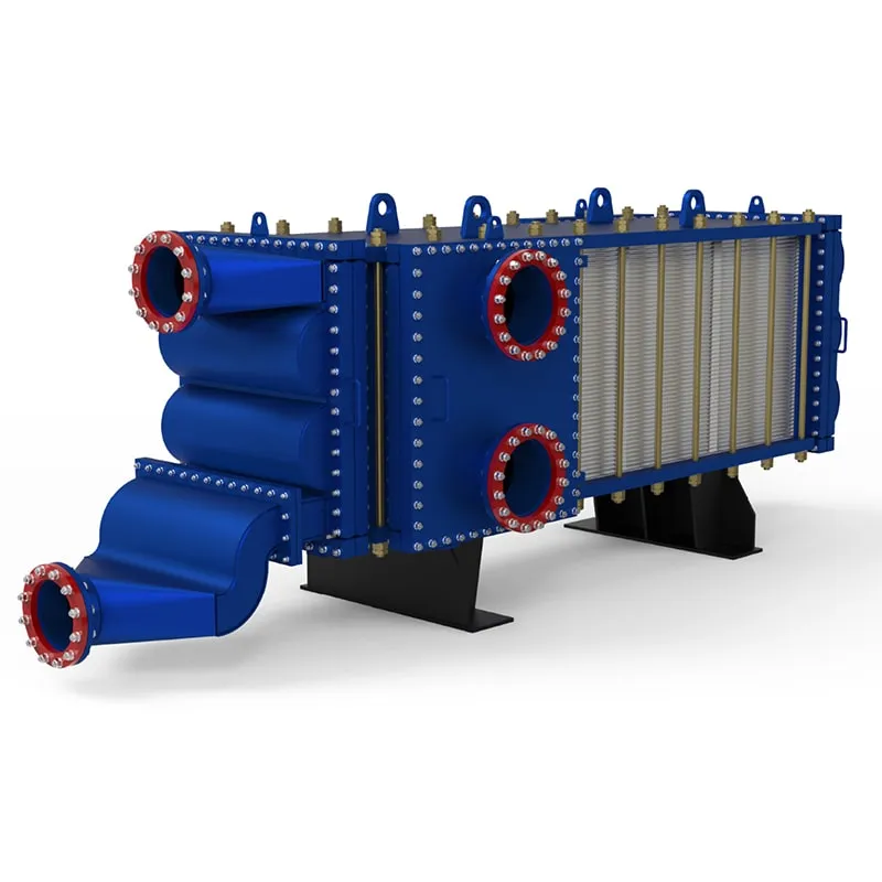
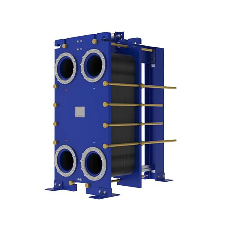
For process engineers and purchasing managers, accurate calculations prevent two common pitfalls: oversizing, which wastes capital and floor space, and undersizing, which leads to inadequate cooling or heating. A reliable design also considers serviceability—gasketed plates allow for easy cleaning and plate replacement, while welded options like the HT-Bloc Welded Plate Heat Exchanger offer leak-free operation for aggressive media.
How Do You Calculate Heat Load for a Plate Heat Exchanger?
Heat load is the foundation of any plate heat exchanger design calculation. The formula is straightforward: Q = m × Cp × ΔT, where Q is the heat duty, m is the mass flow rate, Cp is the specific heat capacity of the fluid, and ΔT is the temperature difference between inlet and outlet. For example, if water flows at 50 kg/s with a Cp of 4.18 kJ/kg·K and a temperature drop of 10°C, the heat load is 2090 kW.
In practice, engineers often work with both hot-side and cold-side data. If the duty is unbalanced—say, the hot fluid releases more energy than the cold fluid can absorb—the calculation must be adjusted. Common industry ranges for plate heat exchangers include:
- Heat duty: 10 kW to 50 MW
- Flow rate: 0.5 to 5000 m³/h
- Operating temperature: -40°C to 200°C (gasketed) or up to 900°C (welded)
- Pressure rating: up to 40 bar (standard), higher for specialized designs
What Role Does Log Mean Temperature Difference Play?
The log mean temperature difference (LMTD) accounts for the varying temperature gradient along the heat exchanger. For countercurrent flow, which is typical in plate heat exchangers, the LMTD is higher than for parallel flow, resulting in a smaller required area. The formula is LMTD = (ΔT1 - ΔT2) / ln(ΔT1/ΔT2), where ΔT1 is the temperature difference at one end and ΔT2 at the other.
A common mistake is assuming a simple average temperature difference. For example, if hot fluid enters at 90°C and exits at 50°C, while cold fluid enters at 20°C and exits at 40°C, the LMTD is approximately 36.4°C—significantly lower than the arithmetic mean of 40°C. Using the correct LMTD ensures the plate count is neither excessive nor insufficient. For multi-pass or complex arrangements, a correction factor (F) is applied, typically ranging from 0.8 to 1.0.
How Is the Overall Heat Transfer Coefficient Estimated?
The overall heat transfer coefficient (U-value) combines the convective resistance on both sides, the conductive resistance of the plate material, and fouling factors. For plate heat exchangers, U-values typically range from 1000 to 7000 W/m²·K for water-to-water applications, and 200 to 1500 W/m²·K for viscous fluids or gases. The formula is 1/U = 1/h_hot + t/k + 1/h_cold + R_f, where h is the film coefficient, t is plate thickness, k is thermal conductivity, and R_f is fouling resistance.
Plate geometry significantly influences the film coefficient. Chevron patterns with high corrugation angles (60° to 65°) create turbulent flow at lower Reynolds numbers, enhancing heat transfer but also increasing pressure drop. For clean fluids, a fouling factor of 0.00005 to 0.0001 m²·K/W is common; for dirty fluids, it may rise to 0.0003 m²·K/W or higher. SHPHE offers free thermal design services to help clients select the optimal plate pattern and material for their specific media.
Pressure Drop: A Critical Constraint in Plate Heat Exchanger Design Calculation
Pressure drop is often the limiting factor in plate heat exchanger design calculation. It is influenced by plate spacing, port size, flow velocity, and the number of passes. A typical allowable pressure drop is 20 to 100 kPa per side, though some applications tolerate up to 150 kPa. The pressure drop across the plates is calculated using the Darcy-Weisbach equation, with friction factors derived from empirical correlations for chevron plates.
High velocity improves heat transfer but increases pumping costs and erosion risk. For water, a velocity of 0.5 to 1.0 m/s in the ports and 0.3 to 0.8 m/s between plates is typical. For viscous fluids, lower velocities are used to avoid excessive pressure drop. Engineers must balance the number of plates and pass arrangement—single-pass configurations minimize pressure drop, while multi-pass designs improve thermal performance at the cost of higher pressure loss.
Material Selection and Plate Geometry in Design Calculation
Plate material directly affects corrosion resistance, thermal conductivity, and cost. Stainless steel (AISI 304, 316L) is the most common, offering good corrosion resistance and a thermal conductivity of about 16 W/m·K. Titanium is used for seawater or chloride-laden fluids, while Hastelloy handles aggressive acids. Gasket materials range from NBR (up to 120°C) to EPDM (up to 150°C) and Viton (up to 200°C).
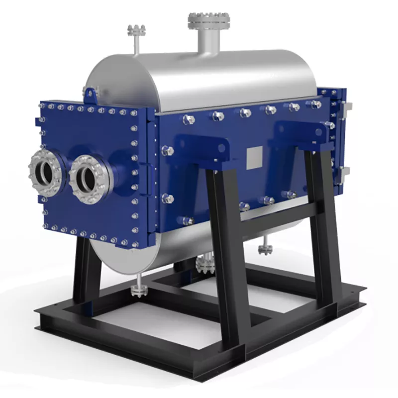
Plate geometry—chevron angle, depth, and pattern—determines the heat transfer coefficient and pressure drop. A 30° chevron angle provides lower turbulence and pressure drop, suitable for viscous fluids, while a 60° angle gives higher turbulence and efficiency for clean fluids. SHPHE manufactures both gasketed and welded designs, including the Wide Gap Welded Plate Heat Exchanger for fibrous or particulate-laden streams, and the Printed Circuit Heat Exchanger (PCHE) for high-pressure, high-temperature applications.
Why Choose SHPHE for Your Plate Heat Exchanger Needs?
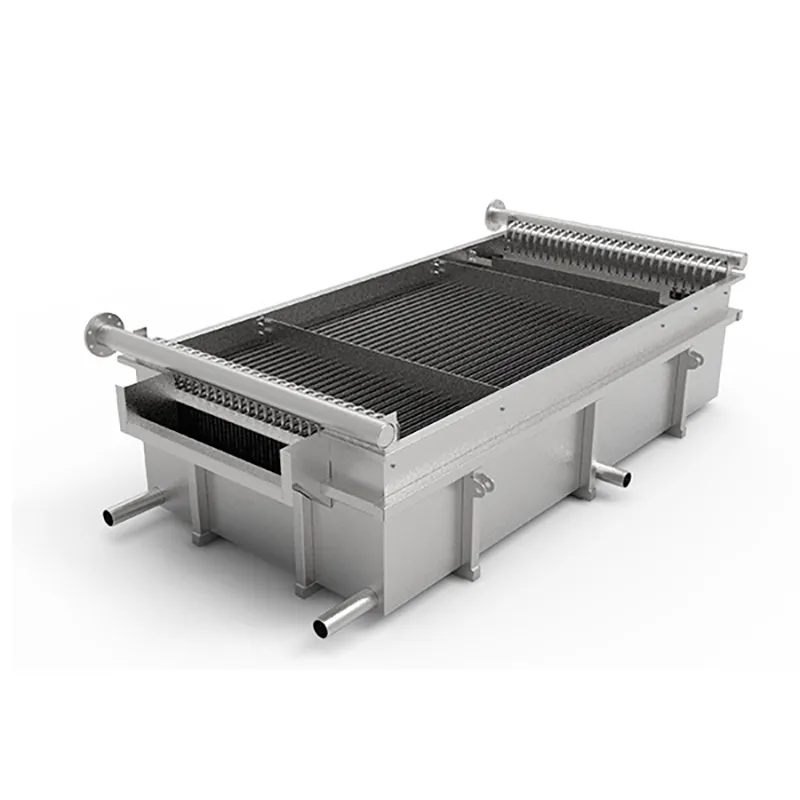
SHPHE, founded in Shanghai in 2005, has been delivering reliable heat transfer solutions to over 20 countries. Our product range includes HT-Bloc and TP Welded Plate Heat Exchangers, Wide Gap Welded units, Gasketed Plate Heat Exchangers, PCHE, Plate Air Preheaters, and Pillow Plates. We hold ISO9001 and ASME U certifications, ensuring every unit meets rigorous quality standards.
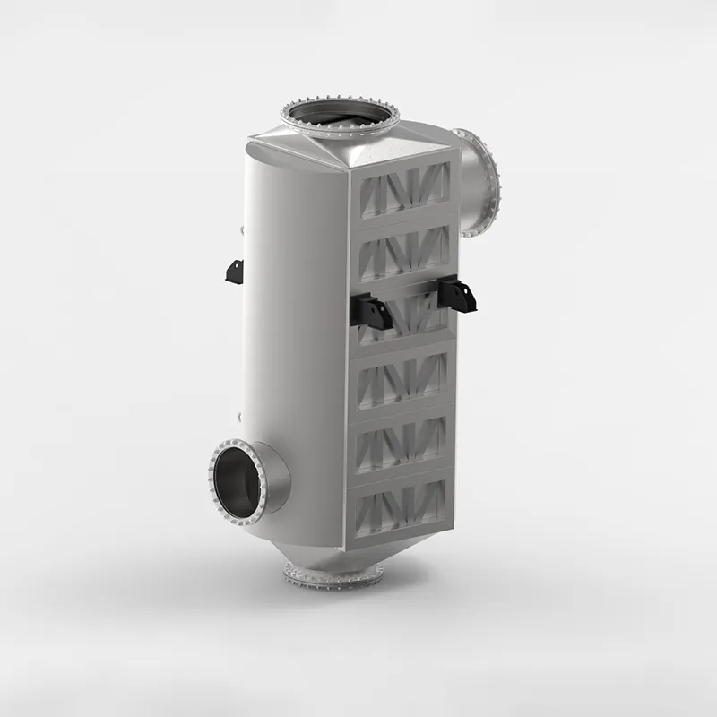
What sets us apart is our free thermal design and selection service. Our engineers perform the plate heat exchanger design calculation for your specific duty, providing a detailed datasheet with plate count, pressure drop, and material recommendations. We also offer alternatives to major brands like Alfa Laval and GEA, ensuring compatibility without compromising performance. For applications requiring high-temperature air preheating, our custom-engineered Plate Air Preheaters are designed for maximum efficiency.
Frequently Asked Questions About Plate Heat Exchanger Design Calculation
What is the first step in a plate heat exchanger design calculation?
The first step is defining the thermal duty: determine the heat load (Q) using flow rate, specific heat, and temperature change of the primary fluid. Without accurate duty data, the rest of the calculation is meaningless. Always verify the mass flow rates and inlet/outlet temperatures from both sides.
How do I choose between a gasketed and a welded plate heat exchanger?
Gasketed units are ideal for clean fluids that require periodic cleaning, as plates can be disassembled. Welded units, such as the TP Welded or HT-Bloc designs, are better for aggressive chemicals, high temperatures, or high pressures where gasket failure is a risk. SHPHE offers both options with free design support.
What is a typical overall heat transfer coefficient for water-to-water applications?
For water-to-water plate heat exchangers, the U-value typically ranges from 1000 to 7000 W/m²·K, depending on plate geometry, flow velocity, and fouling. Clean water with moderate flow yields values around 3000 to 5000 W/m²·K. Always use a safety factor for fouling in real-world conditions.
How do I calculate the number of plates needed?
After determining the required heat transfer area (A = Q / (U × LMTD)), divide by the effective area per plate. Add two to four extra plates for frame ends and possible future capacity. For example, if A = 50 m² and each plate offers 0.5 m², you need about 100 plates plus end plates.
What causes high pressure drop in a plate heat exchanger?
High pressure drop is usually due to excessive flow velocity, narrow plate gaps, or a high chevron angle. Fouling and scaling also increase resistance over time. To reduce pressure drop, consider increasing plate spacing, using a lower chevron angle, or adding parallel flow paths.
Can SHPHE provide a design calculation for my specific application?
Yes, SHPHE offers free thermal design and selection services. Simply provide your flow rates, inlet/outlet temperatures, operating pressure, and media details. Our engineers will perform the plate heat exchanger design calculation and recommend the optimal model, plate count, and material.
Request a Quote for Your Plate Heat Exchanger Design Calculation
Accurate plate heat exchanger design calculation is the key to a cost-effective and reliable thermal system. To get a precise sizing for your project, please provide the following details: flow rate (hot and cold side), inlet and outlet temperatures, operating pressure, and media type (including viscosity and fouling tendency). SHPHE’s engineering team will review your requirements and deliver a tailored solution, whether you need a gasketed unit for easy maintenance or a welded design for demanding conditions. Contact us today to start your free design consultation.

 English EN





User Comments
Service Experience Sharing from Real Customers
Liam
Senior Process EngineerI’ve been using this plate heat exchanger design calculation tool for about six months now, and it’s saved me hours of manual number-crunching. The pressure drop predictions are spot-on compared to our field data. Big fan of the built-in fouling factor adjustments.
Nina
HVAC Design TechnicianHonestly, I’m not the most math-savvy person, but this tool makes plate heat exchanger sizing pretty straightforward. Took me a couple of tries to get the thermal length right, but the help notes are decent. Works great for our chiller systems.
Elena
Maintenance & Reliability ManagerWe use this for retrofitting old plate exchangers in our dairy plant. The heat transfer coefficient calculations match our on-site cleaning schedules perfectly. It’s not just theoretical—it actually helps us predict when we’ll need to re-gasket. Love it.
Oscar
Junior Chemical EngineerIt does the job for basic single-pass designs, but I struggled a bit with multi-pass configurations. The interface could use a clearer input for chevron angles. Still, it’s free and better than doing everything in Excel. Good starting point.