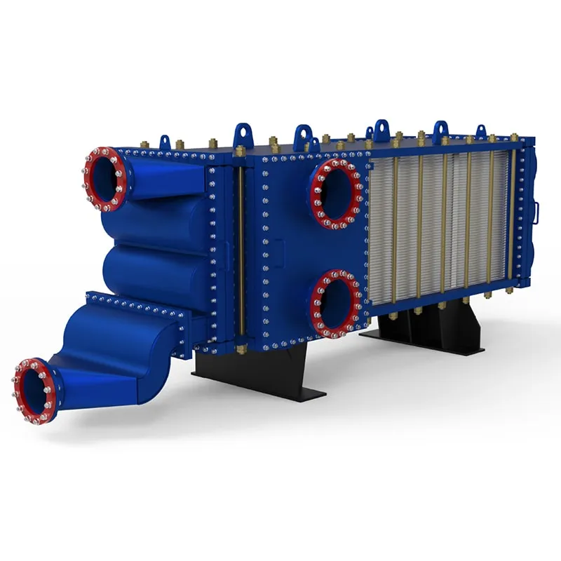
High-Efficiency Cross Flow Plate Heat Exchanger: Top Guide
This guide walks you through the working principles, performance characteristics, and real-world applications of the high-efficiency cross flow plate heat exchanger. Whether you are evaluating a replacement unit for an existing HVAC system or designing a new industrial process line, we cover the key technical details that matter — from heat transfer efficiency and pressure drop to maintenance considerations and selection criteria. No fluff, just the practical information you need to make an informed decision.
What Is a Cross Flow Plate Heat Exchanger?
A cross flow plate heat exchanger is a compact thermal transfer device where two fluid streams flow at right angles to each other across a series of thin, corrugated metal plates. Unlike counterflow or parallel flow configurations, the cross flow arrangement creates a unique temperature profile along the heat transfer surface, which can be advantageous in specific applications where space is tight or where one fluid needs to be brought to a uniform outlet temperature.
The plates are typically made from stainless steel (AISI 304 or 316L), titanium, or other corrosion-resistant alloys depending on the working fluids. Each plate is stamped with a chevron or herringbone pattern that not only increases the effective surface area but also promotes turbulent flow at lower velocities, which enhances the heat transfer coefficient while keeping pressure drop within acceptable limits.
In practical terms, a cross flow plate heat exchanger can achieve heat transfer coefficients in the range of 3,000 to 7,000 W/m²·K for liquid-to-liquid duties, which is significantly higher than what a shell-and-tube unit of comparable size can deliver. This makes them a preferred choice in applications where floor space is at a premium.
Key Design Features and Performance Benefits
The efficiency of a cross flow plate heat exchanger comes down to several well-engineered design features. First, the corrugated plate pattern creates a complex flow path that disrupts the boundary layer, forcing the fluid to constantly change direction. This results in a higher Nusselt number compared to a flat plate, meaning more heat is transferred per unit area.
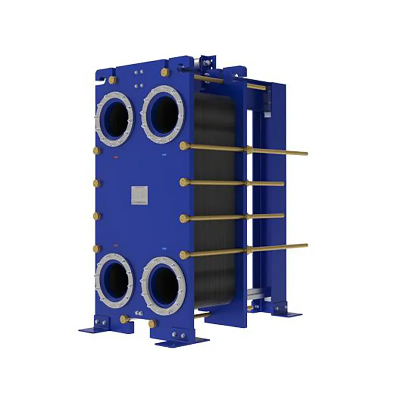
Second, the plates are assembled in a frame with gaskets that direct the fluids into alternating channels. This arrangement allows for true countercurrent flow within each channel pair, even though the overall unit operates in cross flow at the header zones. The result is a log mean temperature difference (LMTD) correction factor that typically ranges from 0.85 to 0.95, which is quite good for a compact exchanger.
Third, the plate pack can be easily expanded or reduced by adding or removing plates. This modularity is a significant operational advantage — if your thermal duty increases in the future, you simply add more plates to the existing frame rather than purchasing a whole new unit. For a deeper look at how different plate configurations compare, you might find this gasketed plate heat exchanger overview helpful.
From a maintenance standpoint, the cross flow design offers easy access to both fluid circuits. The gaskets can be replaced without special tools, and the plates can be individually cleaned or replaced if fouling occurs. This is a major advantage over welded or brazed units where cleaning requires chemical circulation or complete replacement.
Typical Applications Across Industries
Cross flow plate heat exchangers are used in a wide variety of sectors. In HVAC systems, they are commonly found in heat recovery ventilators (HRVs) and energy recovery ventilators (ERVs), where they transfer heat between exhaust air and fresh supply air. The cross flow configuration is particularly well-suited here because it allows for a compact, rectangular unit that fits neatly into ductwork.
In the chemical and pharmaceutical industries, these exchangers handle corrosive fluids where the plate material can be selected to match the chemical compatibility requirements. The ability to inspect both sides of the heat transfer surface makes them suitable for hygienic applications where cross-contamination must be avoided.
The food and beverage sector also relies on cross flow plate heat exchangers for pasteurization and cooling duties. The smooth plate surfaces and the ability to open the unit for thorough cleaning make them compliant with food safety standards. In marine and offshore applications, the compact footprint and corrosion-resistant materials are highly valued.
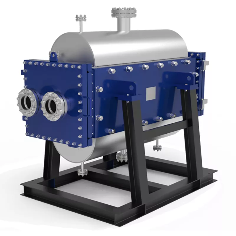
For industrial processes that involve high temperatures and pressures, a welded variant of the plate heat exchanger may be more appropriate. If your operating conditions exceed the limits of gasketed designs, you may want to explore the TP welded plate heat exchanger or the HT Bloc welded plate heat exchanger for more robust solutions.
Performance Data and Efficiency Metrics
When evaluating a cross flow plate heat exchanger, the two most important performance metrics are the overall heat transfer coefficient (U-value) and the pressure drop. The U-value for a typical cross flow plate unit ranges from 2,000 to 5,000 W/m²·K for water-to-water duties, depending on the plate geometry, flow velocity, and fluid properties.
The pressure drop is a function of the plate corrugation angle and the flow velocity. A chevron angle of 30 degrees produces a lower pressure drop but also a lower heat transfer coefficient, while a 60-degree angle provides higher heat transfer at the expense of greater pressure drop. Most manufacturers offer a range of plate patterns so you can optimize the balance between thermal performance and pumping power.
In terms of temperature approach, a cross flow plate heat exchanger can achieve a temperature crossover of as little as 1°C to 2°C, which is remarkable for a compact unit. This close temperature approach is critical in heat recovery applications where every degree of recovered heat translates directly into energy savings.
Selection Criteria: What to Consider Before Buying
Choosing the right cross flow plate heat exchanger involves more than just matching the rated heat load. Here are the key factors you should evaluate:
Fluid compatibility: The plate material must be compatible with both fluids. For chloride-containing water, titanium or a high-molybdenum stainless steel like 254 SMO is often recommended. For clean, non-corrosive fluids, standard 304 stainless steel is usually sufficient and more cost-effective.
Operating pressure and temperature: Gasketed plate heat exchangers are typically rated for pressures up to 25 bar and temperatures up to 180°C. If your process requires higher ratings, you will need to consider welded or semi-welded designs. The printed circuit heat exchanger is an option for extremely high pressures, while wide gap welded plate heat exchangers handle fluids with larger particulates.
Flow rates and allowable pressure drop: You need to know the available pump head and the maximum acceptable pressure drop for each circuit. This will determine the number of passes and the plate pattern. A higher number of passes increases the effective length of the flow path, improving heat transfer but also increasing pressure drop.
Fouling tendency: If your fluids have a tendency to foul, you should select a plate pattern with wider gaps and consider a larger surface area to accommodate the fouling factor. Regular cleaning intervals should be planned, and the unit should be installed with sufficient clearance for plate removal.
Future expansion: One of the biggest advantages of a gasketed plate heat exchanger is that you can add plates later. Make sure the frame you select has the capacity to accommodate additional plates without requiring a new frame. This is a cost-effective way to build in future capacity.
Installation and Maintenance Best Practices
Proper installation is critical to the long-term performance of a cross flow plate heat exchanger. The unit should be mounted on a level foundation with adequate clearance on both sides for plate extraction. Piping should be supported independently to avoid transmitting excessive stress to the exchanger nozzles.
When connecting the piping, it is essential to install strainers upstream of the unit to prevent debris from entering the plate channels. Even small particles can partially block the narrow channels, leading to a significant drop in performance. A 20-mesh strainer is generally recommended for most applications.
Routine maintenance involves periodic inspection of the gaskets for signs of wear or hardening. Gaskets typically last between 5 and 10 years depending on the operating temperature and the chemical compatibility of the fluids. When replacing gaskets, it is important to use the correct adhesive and follow the manufacturer's torque specifications when retightening the plate pack.
For cleaning, the unit can be opened and the plates manually brushed or pressure-washed. For in-place cleaning (CIP), a suitable cleaning solution is circulated through both circuits at an elevated flow rate. The frequency of cleaning depends on the fouling tendency of the fluids, but a visual inspection every six months is a good starting point.
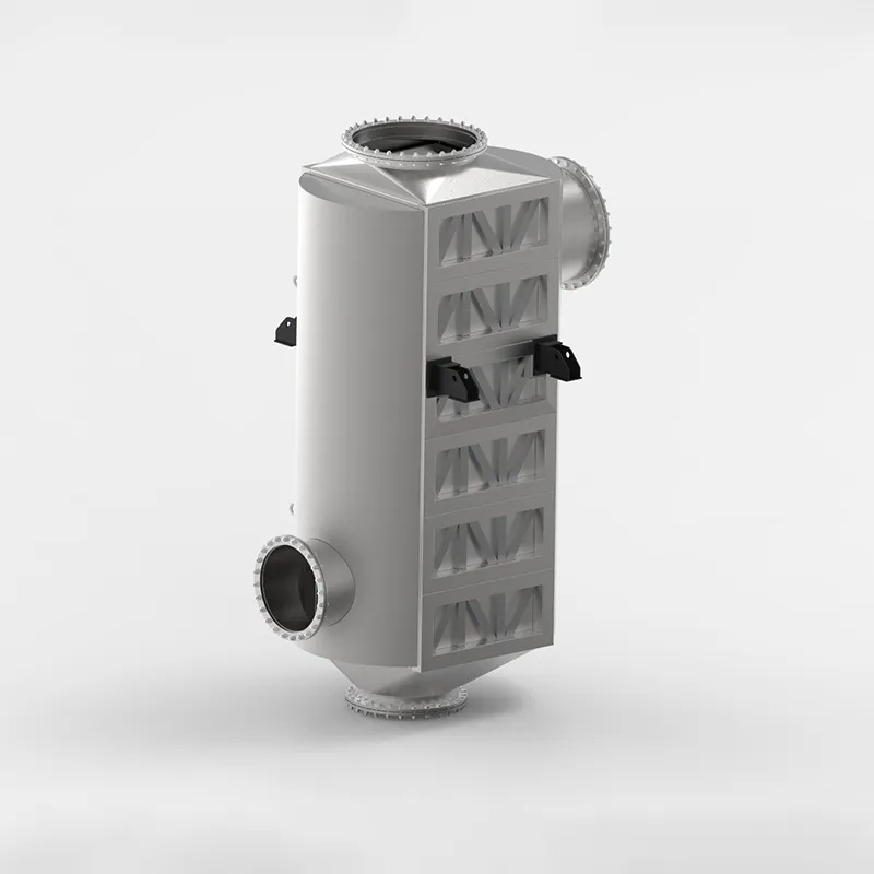
If you are working with specialized process conditions, such as air preheating in a combustion system, you may benefit from a custom-engineered solution. The custom-engineered plate air preheaters and custom-engineered pillow plates offer tailored approaches for unique thermal duties.
Comparing Cross Flow with Other Plate Heat Exchanger Configurations
To make an informed decision, it is useful to understand how a cross flow unit compares with other configurations. In a counterflow plate heat exchanger, the two fluids flow in opposite directions, which yields the highest possible LMTD for a given set of inlet and outlet temperatures. This means that for the same duty, a counterflow unit can be smaller than a cross flow unit.
However, the cross flow configuration offers a distinct advantage in terms of mechanical layout. Because the inlet and outlet nozzles are located on different sides of the unit, piping connections are often simpler and more compact. This can result in significant space savings in tight mechanical rooms or within packaged equipment.
Another consideration is the temperature distribution across the plates. In a cross flow unit, the temperature difference between the two fluids varies across the plate surface, which can cause thermal stresses in certain applications. For highly cyclic thermal loads, a counterflow or parallel flow design may be more forgiving. This is something to discuss with the manufacturer if your process involves frequent start-stop cycles.
For applications where one fluid is a gas and the other is a liquid, the cross flow configuration is often preferred. The gas side typically has a much lower heat transfer coefficient, so the plate pattern can be optimized to enhance turbulence on the gas side without excessively increasing the pressure drop. This is why cross flow plate heat exchangers are so popular in air-to-liquid heat recovery systems.
Energy Efficiency and Sustainability Considerations
From an energy perspective, the high efficiency of a cross flow plate heat exchanger translates directly into lower operating costs. A well-designed unit can recover up to 90% of the waste heat from an exhaust stream, which can significantly reduce the load on primary heating or cooling equipment.
The compact size also means less material is used in manufacturing, which reduces the embodied carbon footprint of the equipment. Additionally, the ability to clean and reuse the plates extends the service life of the unit, reducing the frequency of replacement and the associated waste.
When evaluating the lifecycle cost, it is important to consider not just the initial purchase price but also the pumping energy, maintenance labor, and potential downtime. A slightly more expensive unit with a higher U-value may pay for itself within a few years through reduced pumping costs and lower energy consumption.
Common Pitfalls to Avoid
One of the most common mistakes in selecting a cross flow plate heat exchanger is oversizing the unit. While it may seem prudent to add a safety margin, an oversized unit will operate at lower flow velocities, which reduces the heat transfer coefficient and increases the risk of fouling. It is better to size the unit for the actual design duty and rely on the modularity of the plate pack for future expansion.
Another pitfall is neglecting to account for the viscosity of the fluids at the actual operating temperature. If the fluid is significantly more viscous at startup than at steady-state conditions, the pressure drop may be much higher than anticipated, potentially causing cavitation in the pump or exceeding the frame's pressure rating.
Finally, do not overlook the importance of proper gasket material selection. The gasket must be compatible with both the fluid and the operating temperature. A gasket that is not chemically resistant to the process fluid can swell, harden, or degrade, leading to leaks and premature failure. Always consult the compatibility charts provided by the gasket manufacturer.
Final Recommendations
A high-efficiency cross flow plate heat exchanger is a reliable and cost-effective solution for a wide range of heat transfer duties. Its compact footprint, high thermal performance, and ease of maintenance make it a strong contender for HVAC, industrial, and marine applications.
When selecting a unit, focus on the actual operating conditions rather than the rated capacity. Pay close attention to the fluid properties, allowable pressure drop, and fouling tendency. Work with a manufacturer that can provide detailed performance data and is willing to discuss the nuances of your specific application.
If you are replacing an existing unit, measure the current flow rates and temperatures accurately before contacting a supplier. This will ensure that the new unit is properly sized and that you achieve the expected energy savings. And remember, the modular nature of the plate pack means you can always adjust the capacity later if your process requirements change.
By taking the time to understand the technical aspects covered in this guide, you will be well-equipped to select a cross flow plate heat exchanger that delivers optimal performance for years to come.

 English EN