English EN


How to Choose the Right Printed Circuit Heat Exchanger for Your Process
Select the right printed circuit heat exchanger by matching process needs, pressure, temperature, and fluid compatibility for optimal efficiency and safety.
More
Selecting the correct heat exchanger design is critical for marine engine efficiency. The two most common configurations are shell-and-tube and plate-and-frame, each offering distinct advantages depending on application demands.
This traditional design consists of a cylindrical shell containing a bundle of tubes. One fluid flows through the tubes while the other flows around them within the shell. Shell-and-tube units are highly durable and can handle high pressures and temperatures, making them suitable for harsh marine environments. They are also easier to clean mechanically and are less prone to fouling from seawater or debris.
However, they tend to be larger and heavier than plate designs, and their thermal efficiency is generally lower. For applications where space is limited, this may be a disadvantage. Explore welded plate alternatives for compact needs.
Plate-and-frame designs use a series of corrugated metal plates sealed with gaskets. Fluids flow between alternating plates, creating a large surface area for heat transfer in a compact footprint. This design offers excellent thermal efficiency and is highly customizable by adding or removing plates. It is also lighter and requires less installation space.
The main drawbacks include sensitivity to high temperatures and pressures, and potential gasket failure over time. Regular maintenance is needed to prevent leaks. View gasketed plate exchanger specifications.
Thermal Performance: Plate-and-frame units typically offer higher heat transfer coefficients due to turbulent flow and thinner walls. Shell-and-tube units are less efficient but more robust.
Maintenance & Cleaning: Shell-and-tube designs allow for mechanical cleaning and tube replacement. Plate-and-frame units require gasket replacement and plate inspection, but are easy to disassemble.
Space & Weight: Plate-and-frame exchangers are more compact and lighter, ideal for engine rooms with limited space. Shell-and-tube units are bulkier but more rugged.
Durability: For corrosive seawater applications, shell-and-tube with proper material selection offers longer service life. Wide-gap welded plate options improve fouling resistance.
For high-pressure, high-temperature, or heavily fouling fluids, shell-and-tube remains the preferred choice. For applications prioritizing efficiency, weight savings, and compact design, plate-and-frame is often superior.
Consider the specific cooling medium, flow rates, and maintenance capabilities of your vessel. Printed circuit heat exchangers offer another advanced option.
Consulting with a marine engineer and reviewing OEM recommendations will ensure optimal performance and longevity. Custom pillow plate designs can also be tailored.
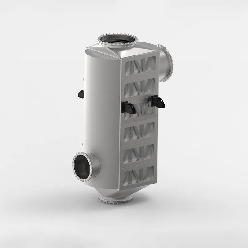
Selecting the correct material for a marine engine heat exchanger is critical to withstand the corrosive nature of seawater. The primary threat is galvanic corrosion, which occurs when dissimilar metals come into contact in a conductive electrolyte like saltwater. Materials must also resist pitting, crevice corrosion, and erosion from suspended particles.
Copper-nickel alloys (90/10 or 70/30) are widely preferred for tube bundles due to their excellent resistance to seawater corrosion and biofouling. They form a protective oxide layer that self-repairs in clean seawater. For the shell and end caps, nickel-aluminum bronze or stainless steel grades like 316L are common choices, offering high strength and durability in marine environments.
Titanium is another premium option, providing near-immunity to seawater corrosion, though at a higher cost. It is often used in high-performance or long-life systems. Always verify material compatibility with the engine coolant side as well, ensuring no galvanic couple forms between the heat exchanger and engine block. Proper material selection directly impacts the unit's lifespan and operational reliability in saltwater conditions.
Proper sizing of a marine engine heat exchanger is critical for maintaining optimal operating temperatures. An undersized unit leads to overheating, while an oversized one causes inefficient thermal regulation. The key is to match the heat exchanger's cooling capacity to the engine's maximum continuous load.
To calculate the required cooling capacity, use the formula: Q = m × Cp × ΔT, where Q is the heat rejection rate (kW), m is the coolant mass flow rate (kg/s), Cp is the specific heat capacity of the coolant, and ΔT is the temperature difference between inlet and outlet. Always factor in a safety margin of 10-15% for fouling and future upgrades.
| Engine Power (HP) | Heat Rejection (kW) | Min. Flow Rate (L/min) | Recommended Surface Area (m²) |
|---|---|---|---|
| 100 - 200 | 75 - 150 | 60 - 120 | 1.5 - 3.0 |
| 200 - 400 | 150 - 300 | 120 - 240 | 3.0 - 6.0 |
| 400 - 800 | 300 - 600 | 240 - 480 | 6.0 - 12.0 |
| 800 - 1600 | 600 - 1200 | 480 - 960 | 12.0 - 24.0 |
The table above provides general sizing benchmarks for marine diesel engines operating under typical sea water conditions. For high-performance or heavily loaded engines, consider selecting a heat exchanger with 20% greater surface area than the baseline recommendation. Additionally, verify that the unit's pressure drop does not exceed the engine manufacturer's specified limit, typically ranging from 0.3 to 0.7 bar.
For custom applications, consult detailed engineering data from reputable manufacturers. Explore custom engineered plate air preheaters or gasketed plate heat exchangers for modular solutions. For extreme marine environments, TP welded plate heat exchangers offer enhanced durability and thermal performance.
Proper maintenance is essential for maximizing the lifespan and efficiency of a marine engine heat exchanger. When evaluating a unit, consider how easily it can be accessed for inspection and service. A well-designed exchanger allows technicians to reach all critical components without dismantling surrounding systems, reducing downtime and labor costs.
Regular cleaning is a key factor in preventing fouling and scaling, which can degrade thermal performance. Look for models with removable end covers or easy-to-clean tube bundles that simplify the removal of salt deposits, debris, or organic growth. Some designs offer self-cleaning features or chemical cleaning ports for more efficient maintenance.
Service intervals vary based on operating conditions, but a quality heat exchanger should have recommended schedules that align with typical marine usage. Shorter intervals may indicate a design prone to clogging or corrosion. Evaluate the manufacturer’s guidelines for anode replacement, gasket checks, and pressure testing to ensure long-term reliability.
For more detailed specifications and maintenance recommendations, visit the product page for professional guidance.
Proper installation and system integration of a marine engine heat exchanger are critical to achieving optimal performance and long-term reliability. The primary goal is to ensure smooth, unobstructed flow paths for both the coolant and the raw water circuits. Even a high-quality heat exchanger can underperform if flow dynamics are compromised by poor piping design or incorrect placement. Key considerations include minimizing sharp bends, avoiding unnecessary restrictions, and maintaining consistent pipe diameters to prevent pressure drops that reduce flow rates and heat transfer efficiency.
One of the most common pitfalls in marine installations is the misalignment of inlet and outlet connections, which can lead to air pockets or cavitation. Air trapped in the system not only reduces cooling capacity but can also cause localized overheating and damage to the engine. To avoid this, ensure that the heat exchanger is mounted at the correct angle and that all vent points are positioned at the highest locations in the circuit. Additionally, always follow the manufacturer's recommended flow direction, as reversing the flow can drastically reduce thermal performance and increase fouling risks.
Another critical aspect is the integration of supporting components such as expansion tanks, pressure relief valves, and bypass lines. These elements must be sized and placed correctly to maintain stable system pressure and accommodate thermal expansion. For instance, an improperly sized expansion tank can cause pressure spikes that stress the heat exchanger plates or tubes. Similarly, a bypass loop that is too restrictive may force excessive flow through the heat exchanger, leading to erosion or vibration issues. It is essential to model the entire system hydraulically when possible, accounting for all resistances and pump capacities.
Material compatibility and corrosion resistance are also vital in the marine environment. The heat exchanger materials must be matched with the piping and fittings to avoid galvanic corrosion. Use appropriate dielectric unions or sacrificial anodes where dissimilar metals are connected. Furthermore, ensure that all gaskets, seals, and hoses are rated for the expected temperature and pressure ranges, as well as resistant to saltwater and coolant chemicals. Regular inspection of these components during installation can prevent costly failures later.
Finally, consider the accessibility of the heat exchanger for maintenance. Marine engine rooms are often cramped, but the installation should allow for easy removal of end covers or tube bundles for cleaning and inspection. Leave adequate clearance around the unit and avoid placing it directly under other components that might drip oil or water onto it. For detailed guidance on selecting and integrating heat exchangers, refer to resources such as custom engineered plate air preheaters or gasketed plate heat exchangers for specific marine applications.
Shell-and-tube heat exchangers offer robust construction and tolerance to high pressures, making them suitable for heavy-duty marine applications. Plate-and-frame designs provide superior thermal efficiency in a compact footprint, ideal for space-constrained installations. The choice depends on operating pressure, maintenance access, and desired heat transfer rate.
Seawater environments demand materials such as 90/10 copper-nickel, stainless steel (316L or duplex), or titanium for tube bundles and plates. Avoid galvanic corrosion by matching material couples and ensuring adequate sacrificial anodes. Proper material selection directly extends heat exchanger life and reduces fouling.
Calculate required heat rejection using engine power, fuel consumption, and coolant flow rate. Oversizing reduces efficiency and increases cost; undersizing leads to overheating. Always consider peak load conditions, seawater temperature variations, and fouling factors to achieve reliable thermal performance.
Choose designs that allow easy access to tube bundles or plates for mechanical cleaning or backflushing. Plate-and-frame units simplify gasket replacement and plate addition. Routine inspection intervals should align with seawater quality and engine operating hours to prevent scaling and blockages.
Ensure proper flow direction (counterflow preferred), adequate pump head, and correct piping diameter to avoid cavitation and air entrapment. Locate the heat exchanger below the engine’s coolant outlet to facilitate natural circulation. Verify alignment with existing seawater strainers and valves for streamlined servicing.
Selecting the right marine engine heat exchanger requires balancing thermal efficiency, material compatibility, and serviceability. Prioritize corrosion-resistant alloys, accurate sizing based on engine load, and designs that simplify cleaning. Proper integration into the cooling loop ensures reliable operation and extended service life in harsh marine conditions.
We provide you with comprehensive foreign trade solutions to help enterprises achieve global development
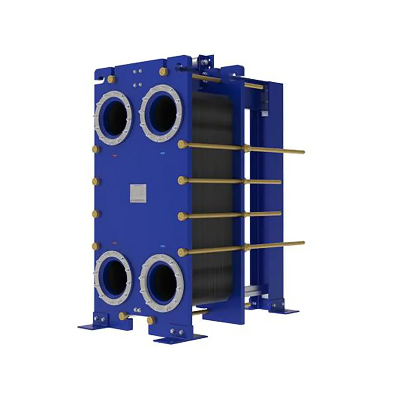
Since the invention of the plate heat exchanger (PHE) in 1923, thermal technology has evolved from standard food-grade processing to highly complex industrial operations. At SHPHE, we take this classic, versatile design and transform it into highly bespoke heat transfer solutions tailored to your unique process fluids and thermal loads. While traditional gasketed PHEs offer high efficiency and compact footprints, SHPHE optimizes plate corrugations, metallurgy, and sealing systems to handle your specific chemical, HVAC, or energy recovery parameters. Our custom-engineered gasketed plate heat exchangers provide outstanding scalability and ease of maintenance, serving as an indispensable asset for heavy industries—including oil and gas, metallurgy, and food processing—where uptime, energy recovery, and long-term sustainability are top priorities.
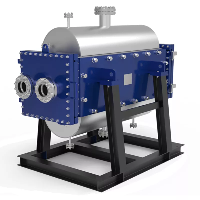
Industrial processes involving particle-laden slurries, high-viscosity syrups, or fiber-rich pulp demand more than standard equipment—they require target-engineered thermal management. At SHPHE, we configure the TP Welded Plate Heat Exchanger to directly conquer your plant's severe fouling, blockage, and erosion threats. Combining custom-tailored channel geometries, wear-resistant metallurgy, and integrated CIP (Cleaning-in-Place) systems, we deliver absolute production continuity where conventional heat exchangers fail.
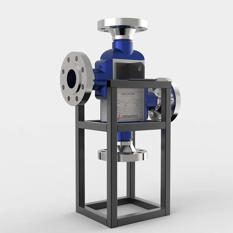
The SHPHE Printed Circuit Heat Exchanger (PCHE) represents a paradigm shift in microchannel thermal management, meticulously engineered for the world's most critical and demanding industrial boundaries. Developed to surpass the physical limitations of conventional shell-and-tube designs in ultra-high-pressure environments, our custom PCHEs integrate advanced photochemical etching and solid-state diffusion bonding to provide unmatched safety, thermal efficiency, and integrity under extreme stress. Initially deployed within high-consequence sectors such as aerospace and nuclear power generation, PCHE technology has completely revolutionized high-density thermal processing. Today, SHPHE brings this breakthrough engineering to mainstream energy transitions—including LNG liquefaction, supercritical CO² power cycles, hydrocarbon processing, and high-pressure hydrogen systems—enabling plants to maximize energy recovery, ensure zero-leakage security, and significantly shrink environmental footprints.
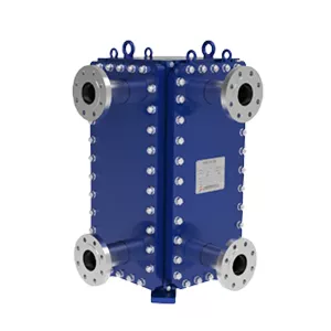
Custom-Engineered for Severe Process Demands. At SHPHE, we don't just supply equipment; we design tailored thermal solutions. Our HT-Bloc welded plate heat exchangers are custom-configured by our experienced engineers to overcome your specific industry challenges—whether handling high-viscosity media, extreme temperatures, or strict space constraints.